
Method and apparatus for transmitting control information in wireless communication systems

a wireless communication system and control information technology, applied in the direction of wireless communication, transmission path division, wireless communication, etc., can solve the problems of legacy cdd transmission based on crs transmission not being configured, and the improvement of lte/lte-a systems is severely limited, so as to achieve reliable information transfer and higher diversity order

Active Publication Date: 2014-07-03
SAMSUNG ELECTRONICS CO LTD
View PDF6 Cites 8 Cited by
  • Summary
  • Abstract
  • Description
  • Claims
  • Application Information

AI Technical Summary

Benefits of technology

This patent is about a way to send signals in a way that allows them to be received with less interference, even in mobile environments that change quickly. The system splits the wireless resources used for sending control channels, and assigns different antenna ports to each segment. The user equipment uses a mapping system to figure out how to precodel and channel estimate for each segment, based on the mapping between multiple wireless resources and antenna ports. This allows for better information transfer even in challenging mobile environments.

Problems solved by technology

Furthermore, with frequent MU-MIMO transmissions where multiple UEs can be scheduled using the same frequency and time resources, the improvement on LTE / LTE-A systems is severely limited due to the shortage of PDCCH capacity.
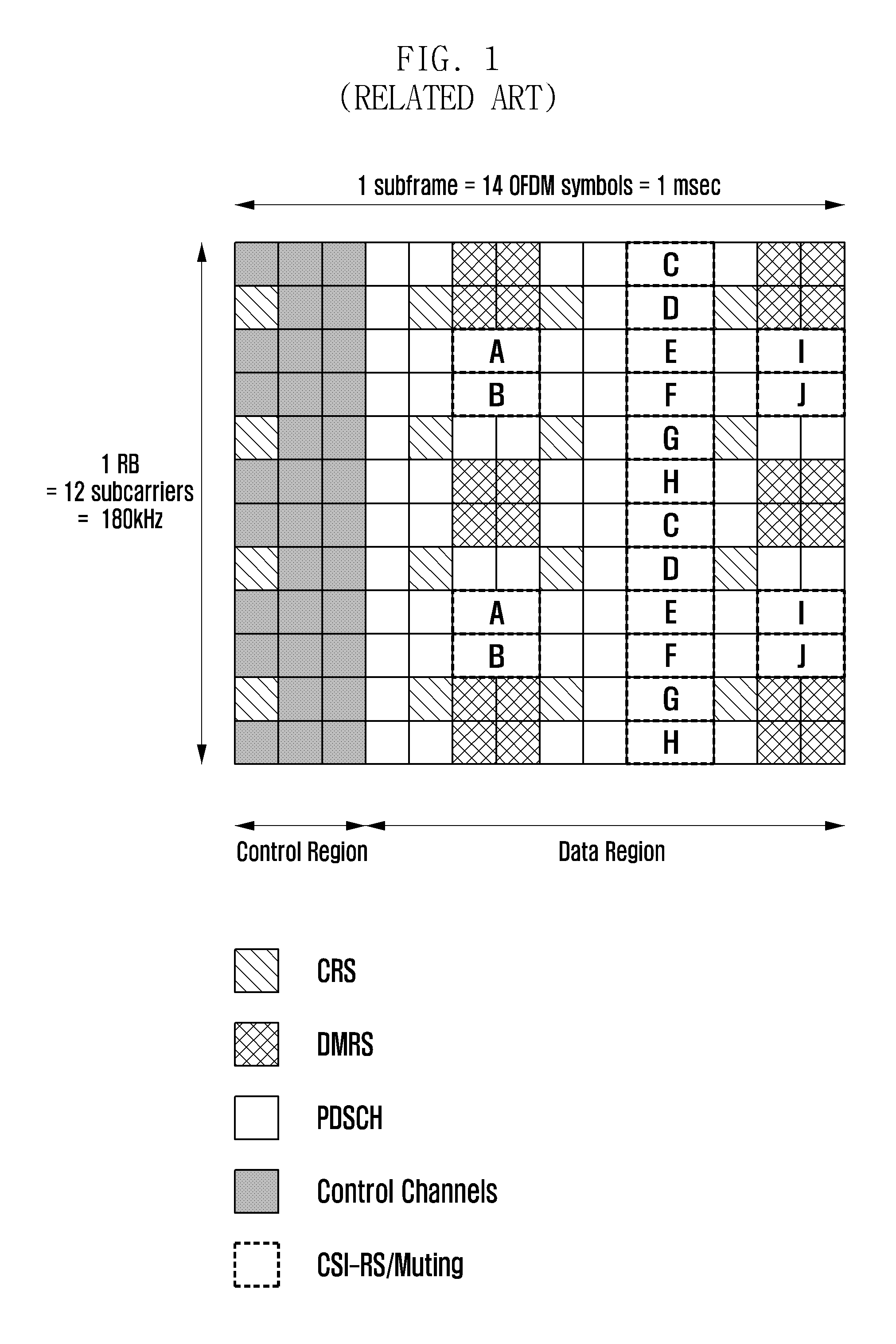
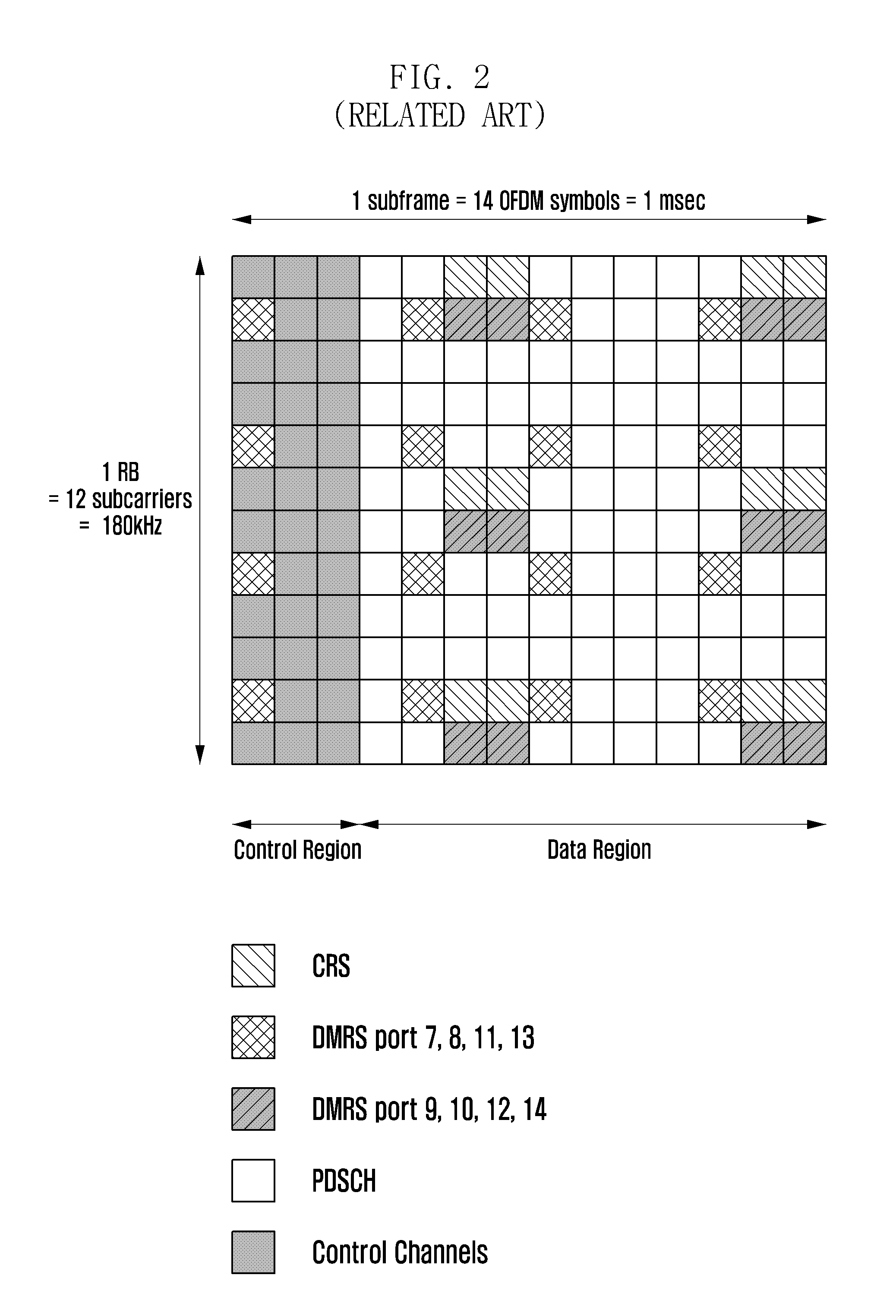
However, in a MBSFN subframe where no CRS is defined, the legacy CDD transmission based on CRS transmission can no longer be configured.
But such an open loop MIMO technique is still necessary in some scenarios when the feedback is not readily available or reliable, and / or the MIMO channel is rather selective in frequency and / or time domain.

Method used


Image

  • Method and apparatus for transmitting control information in wireless communication systems
  • Method and apparatus for transmitting control information in wireless communication systems
  • Method and apparatus for transmitting control information in wireless communication systems

Examples


exemplary embodiment 1

REG Based Precoding Cycling

[0067]A unified precoding definition can be defined similar to the large delay Cyclic Delay Diversity (CDD) in legacy systems:

[y(7)(i)⋮y(6+v)(i)]=W(i)D(i)U[x(0)(i)⋮x(v-1)(i)].

[0068]For non-CDD transmission, one can define D(i)=U=Iv, where Iv is the identity matrix, so that the precoding is simplified to:

[y(7)(i)⋮y(6+v)(i)]=W(i)[x(0)(i)⋮x(v-1)(i)].

[0069]Note that exemplary embodiments of the present invention can be applied with both the CDD and non-CDD precoding as defined above. An exemplary embodiment of the present invention discloses methods of how W(i) is determined for each symbol.

[0070]In an exemplary embodiment of the present invention, the system assigns a set of REGs for control or data transmission for a particular UE. The resource allocation of the set of REGs can be previously indicated to the UE, or the UE may identify the allocation by blind decoding a limited number of possible resource combinations.

[0071]Assume N REGs are assigned to the U...

exemplary embodiment 2

REG and DMRS Port Cycling

[0091]In the previously described exemplary embodiment 1, W(i) is decided based on the REG location / index. It should be assumed that the UE knows the exact W(i) being applied for each REG.

[0092]In an exemplary embodiment of the present invention, the UE can decode the transmission by using precoded DMRS without knowledge of which W(i) is used for each REG. The UE should assume the precoding for spatial multiplexing using antenna ports with UE-specific reference signals in the legacy system, which is defined as:

[y(7)(i)⋮y(6+v)(i)]=[x(0)(i)⋮x(v-1)(i)].

[0093]For each REG, the UE should assume it is transmitted using a specific DMRS. Rules should be designed so that the UE knows the DMRS port configuration for each REG.

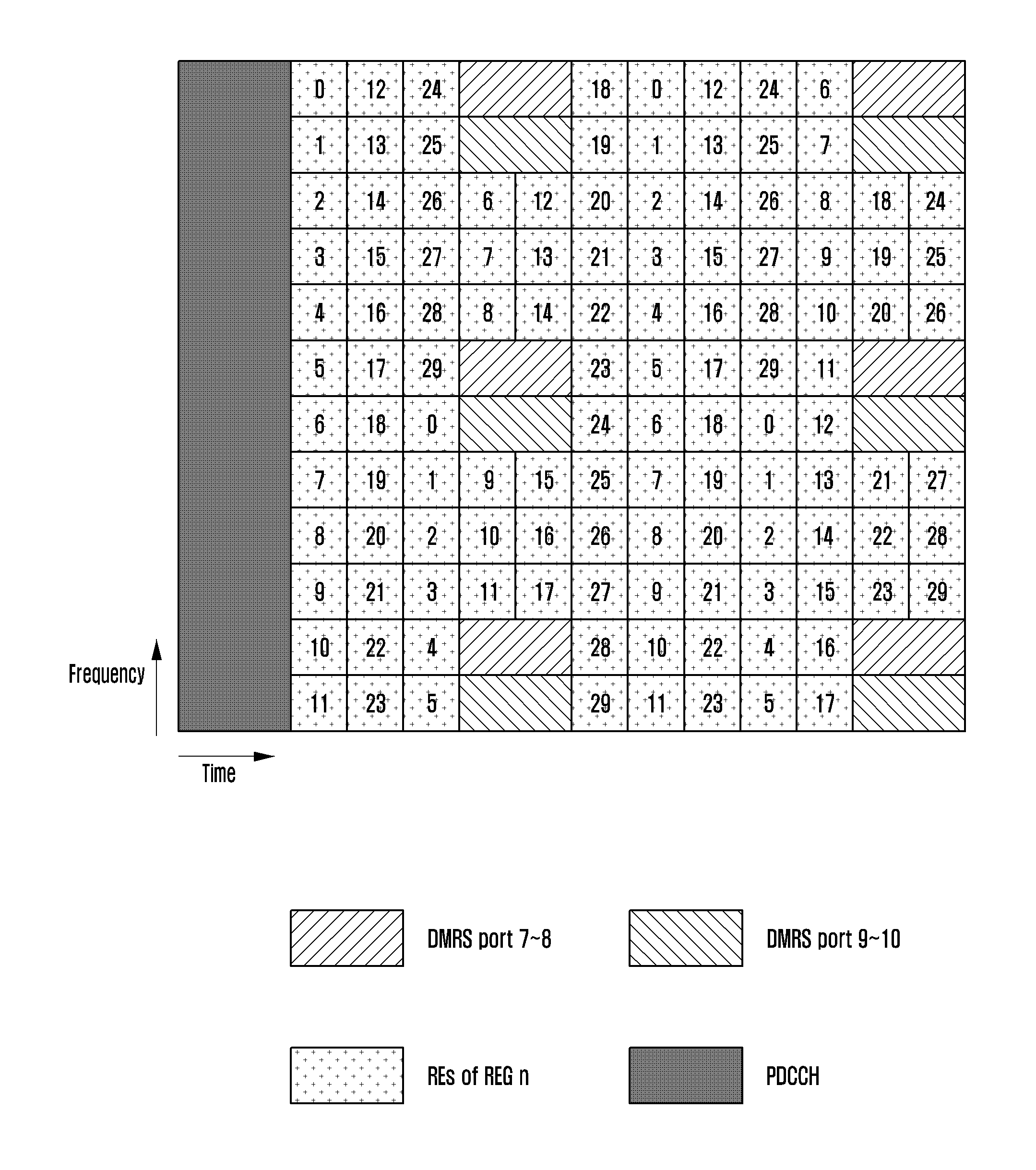
[0094]FIG. 8 is a diagram illustrating precoder cycling allocation with a predefined DMRS mapping according to an exemplary embodiment of the present invention.

[0095]Referring to FIG. 8, precoding allocation with predefined DMRS mapping, where REG...


PUM


Abstract

A method for transmitting control information by a base station in a wireless communication system is provided. The method includes determining a precoder to be applied to a resource and a Demodulation Reference Signal (DMRS) port, the resource being used to transmit the control information, and the DMRS port corresponding to the resource and being used to transmit a DMRS, precoding the resource and the DMRS port by using the determined precoder, and transmitting the control information and the DMRS to a user equipment.

Description

CROSS-REFERENCE TO RELATED APPLICATIONS[0001]This application is a continuation application of a U.S. patent application Ser. No. 13 / 679,086, filed on Nov. 16, 2012, which claims the benefit under 35 U.S.C. §119(e) of a U.S. provisional patent application filed on Nov. 16, 2011 in the U.S. Patent and Trademark Office and assigned Ser. No. 61 / 560,454 and a U.S. provisional patent application filed on Jan. 17, 2012 in the U.S. Patent and Trademark Office and assigned Ser. No. 61 / 587,351, the entire disclosure of each of which is hereby incorporated by reference.BACKGROUND OF THE INVENTION[0002]1. Field of the Invention[0003]The present invention relates to a method and an apparatus for transmitting control information in wireless communication systems. More particularly, the present invention relates to a method for providing a transmission scheme that allows the transmitted signals to be received with a higher level of diversity order such that reliable transfer of information can be...

Claims


Application Information

Patent Timeline
Patent Type & Authority Applications(United States)
IPC IPC(8): H04W72/04
CPCH04W72/0406H04B7/0456H04L5/0007H04L5/0053H04L27/00H04W72/23H04L5/0051H04L5/0023H04W72/0453H04L1/02H04L1/00H04W72/20
Inventor KIM, YOUNSUNSHAN, CHENGLEE, JUHOLEE, HYOJINKIM, KIILCHO, JOONYOUNGJI, HYOUNGJURO, SANGMINCHOI, SEUNGHOON
Owner SAMSUNG ELECTRONICS CO LTD
Learn More