Distributed packet switching in a source routed cluster server

a cluster server and packet switching technology, applied in the field of processing systems, can solve the problems of device failure, latency and bandwidth bottleneck, and limit the scalability of such networks

Active Publication Date: 2014-07-03
ADVANCED MICRO DEVICES INC
View PDF5 Cites 62 Cited by
  • Summary
  • Abstract
  • Description
  • Claims
  • Application Information

AI Technical Summary

Problems solved by technology

However, as a single centralized switch is involved in conducting all traffic, this approach is susceptible to faults or device failure, and can serve as a latency and bandwidth bottleneck.
Moreover, each switch in the network fabric stores the routing information for every path that traverses the switch, which leads to relatively large routing tables at each switch and thus limits the scalability of such networks.
Also, as L2 Ethernet switch networks are conventionally constructed as a tree topology, the root switch node in the tree topology is often the bandwidth limiter, and thus the typical solution is to employ a very large and expensive root switch node.

Method used


Image

  • Distributed packet switching in a source routed cluster server
  • Distributed packet switching in a source routed cluster server
  • Distributed packet switching in a source routed cluster server

Examples


Embodiment Construction

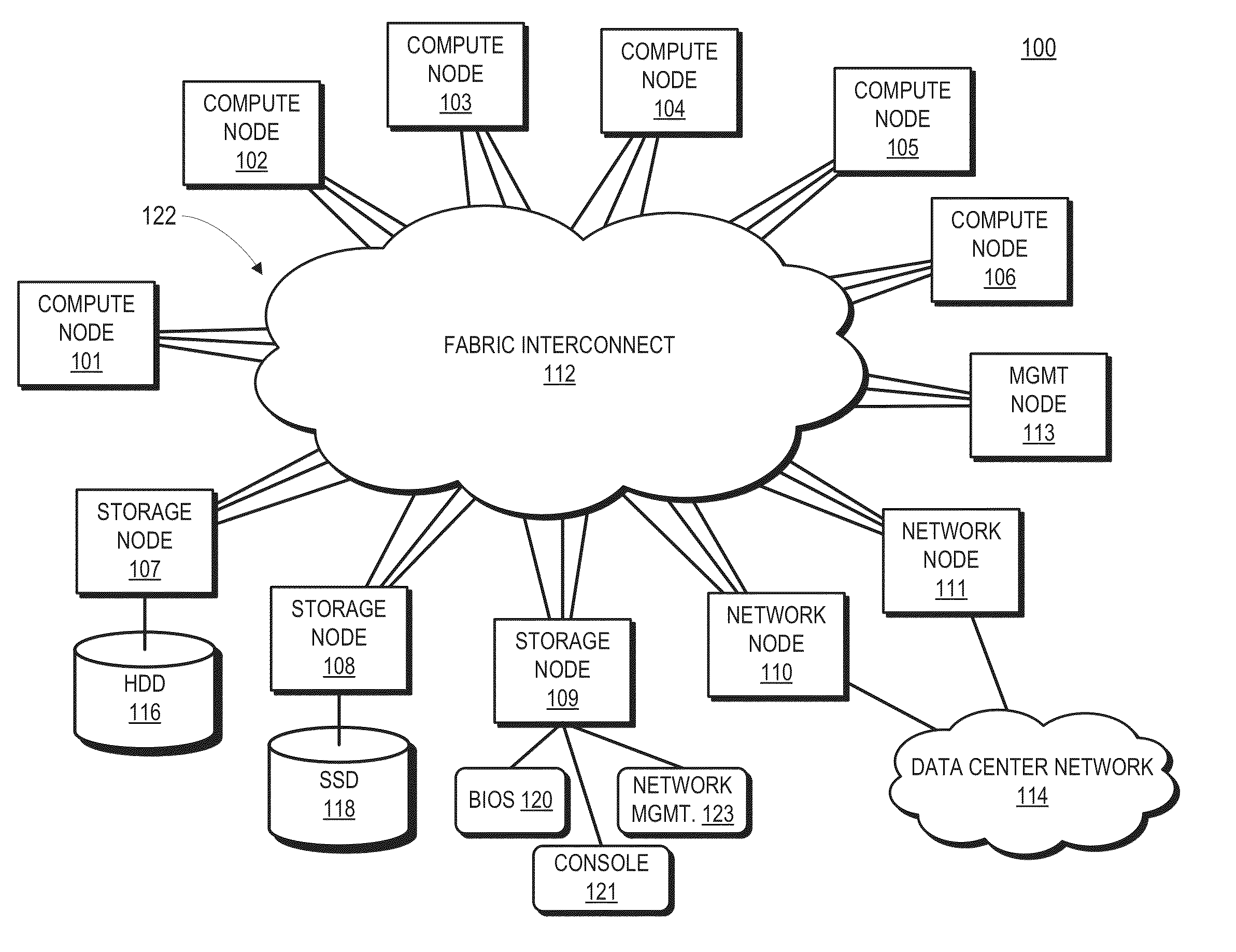
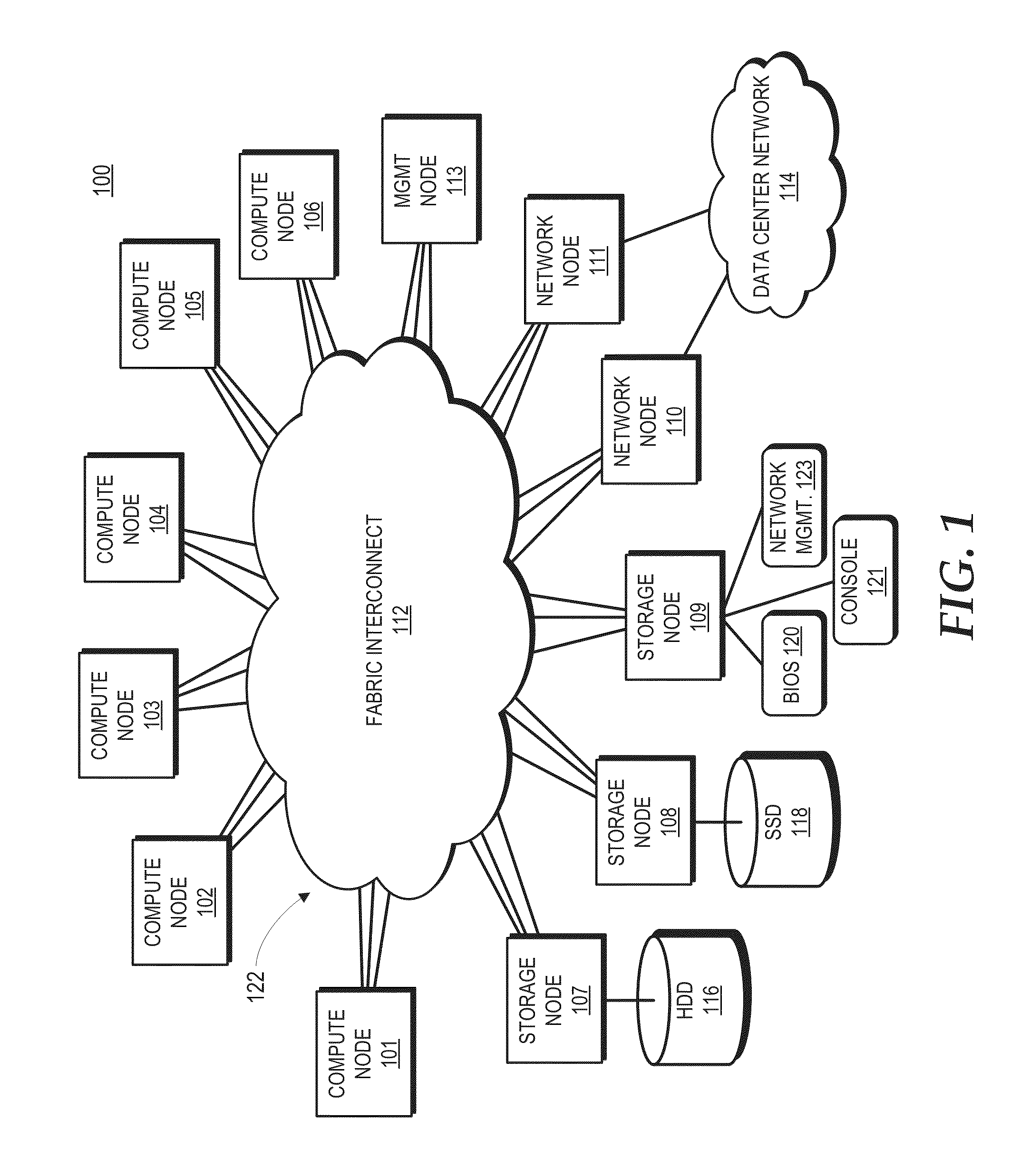
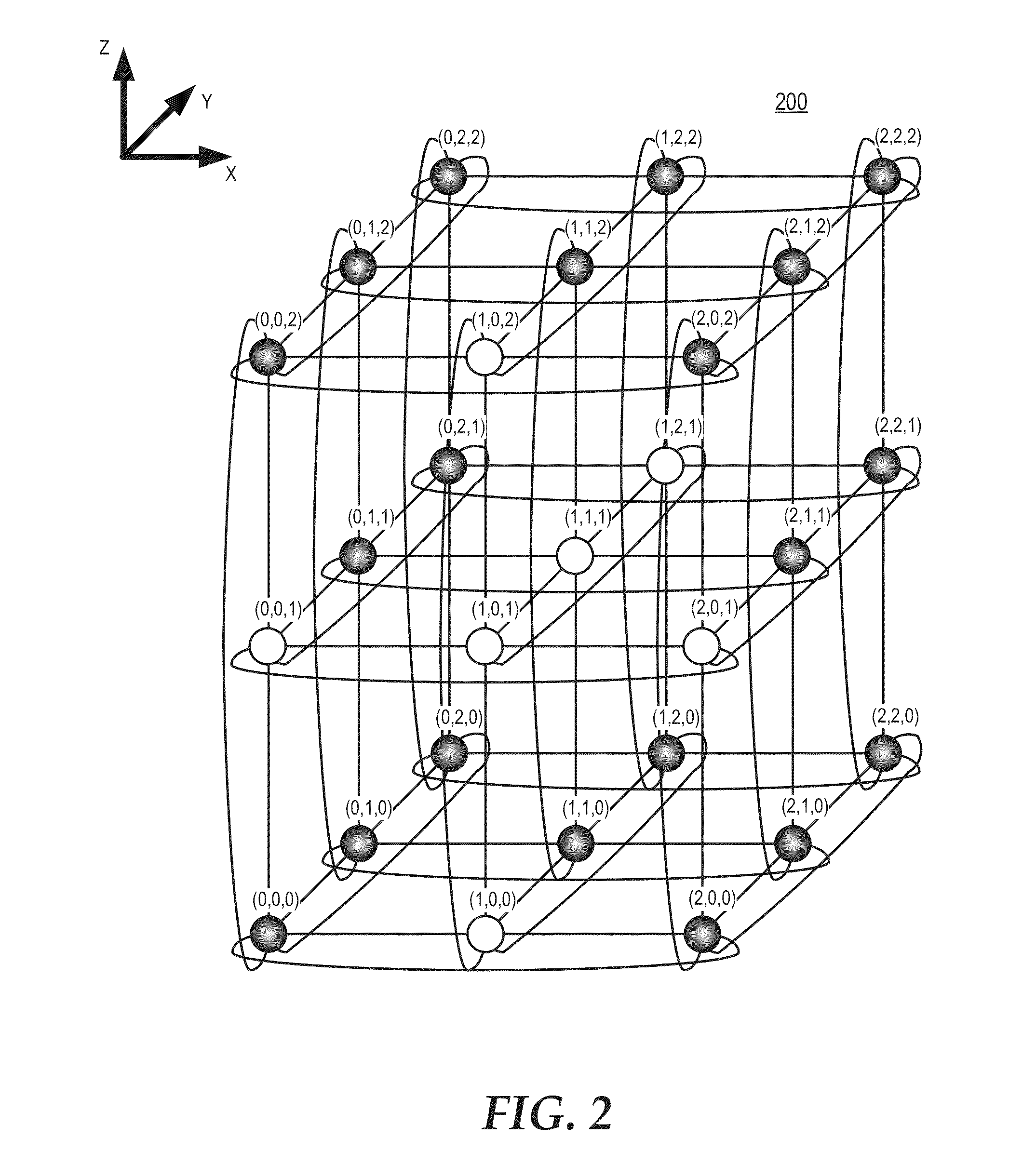
[0016]FIGS. 1-10 illustrate a cluster compute server employing distributed packet switching in a fabric that interconnects nodes in a mesh network topology. In some embodiments, the fabric is a source routed fabric such that packets are routed over the fabric using deterministic routing paths. To illustrate, the mesh network topology can comprise a three-dimensional (3D) torus topology, and packets are routed over the fabric using a strict deterministic dimensional-order routing (that is, packets traverse completely in one dimension on the routing path between source node and destination node before moving to another dimension in the 3D torus). The location of each node in the mesh network topology is represented by a location identifier that also serves as a source routing control that specifies the source routed path between the source node and the destination node. The location identifiers can be implemented as, for example, media access control (MAC) addresses or other types of ...


PUM


Abstract

A cluster compute server includes nodes coupled in a network topology via a fabric that source routes packets based on location identifiers assigned to the nodes, the location identifiers representing the locations in the network topology. Host interfaces at the nodes may be associated with link layer addresses that do not reflect the location identifier associated with the nodes. The nodes therefore implement locally cached link layer address translations that map link layer addresses to corresponding location identifiers in the network topology. In response to originating a packet directed to one of these host interfaces, the node accesses the local translation cache to obtain a link layer address translation for a destination link layer address of the packet. When a node experiences a cache miss, the node queries a management node to obtain the specified link layer address translation from a master translation table maintained by the management node.

Description

BACKGROUND[0001]1. Field of the Disclosure[0002]The present disclosure relates generally to processing systems and more particularly to packet switching in a cluster server.[0003]2. Description of the Related Art[0004]Cluster servers (also commonly referred to as “cluster computers”) are composed of a number of nodes linked together via a network fabric and which typically cooperate to perform shared tasks. Conventionally, the compute nodes of a cluster server are interconnected via a shared link layer, or “layer 2”, switch that serves as the hub for all inter-node communications. The switch employs at least one port per compute node, and forwards packet traffic between the ports based on a single large unified routing table. However, as a single centralized switch is involved in conducting all traffic, this approach is susceptible to faults or device failure, and can serve as a latency and bandwidth bottleneck. Moreover, each switch in the network fabric stores the routing informat...

Claims


Application Information

Patent Timeline
Patent Type & Authority Applications(United States)
IPC IPC(8): H04L12/56H04L45/74
CPCH04L49/25H04L45/74H04L45/34H04L45/66H04L45/742H04L45/54H04L49/356
Inventor LIE, SEANDITYA, VIKRAMALAUTERBACH, GARY R.
Owner ADVANCED MICRO DEVICES INC
Why Eureka
Try Eureka