Lock

a technology of locking and assembly, applied in the direction of ropes and cables for vehicles/pulleys, mechanical machines/dredgers, shackles, etc., can solve the problems of needing to replace the whole device, the operation of the digging device is typically subject to harsh conditions, and the excavating bucket or other digging device or equipment is typically subject to large forces, so as to achieve good retention performance in the operation of the equipment

Inactive Publication Date: 2014-07-03
BRADKEN RESOURCES
View PDF9 Cites 16 Cited by
  • Summary
  • Abstract
  • Description
  • Claims
  • Application Information

AI Technical Summary

Benefits of technology

[0013]Embodiments of the locking assemblies, elements, and systems have particular application for use in excavating equipment and al

Problems solved by technology

Excavating buckets or other digging devices or equipment are typically subject to harsh conditions.
Digging devices typically experience large forces during digging and excavation operations.
This reduces the need to replace the whole device if the lip edge became worn, which would be much more costly than replacing just the shrouds.
Again these components are subject to very harsh operational conditions and accordingly the components need to be designed to operate in such harsh conditions.
In heav

Method used


Image

  • Lock
  • Lock
  • Lock

Examples


first embodiment

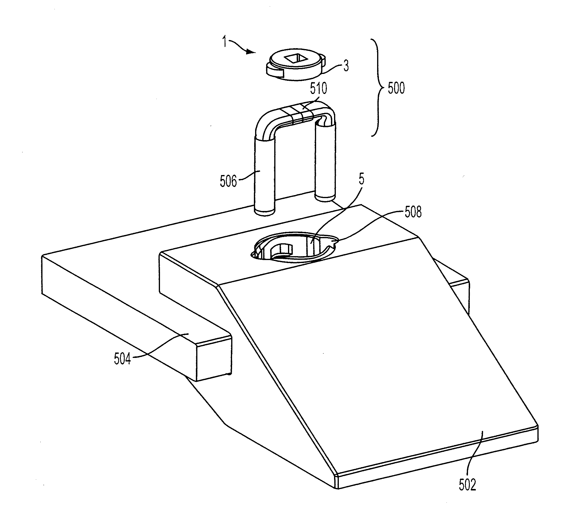
[0055]FIGS. 1A and 1B are exploded perspective views of a lock assembly according to a

[0056]FIG. 1B illustrates a lock assembly 1 comprising the locking element 3 of FIG. 1A and a retaining member which in the illustrative form is a locking ring 7 of FIG. 1B. The locking ring 7 incorporates a cavity 23 having an interior locking surface 5 and the locking element is received in the cavity and engagable with the locking surface as will be described in more detail below.

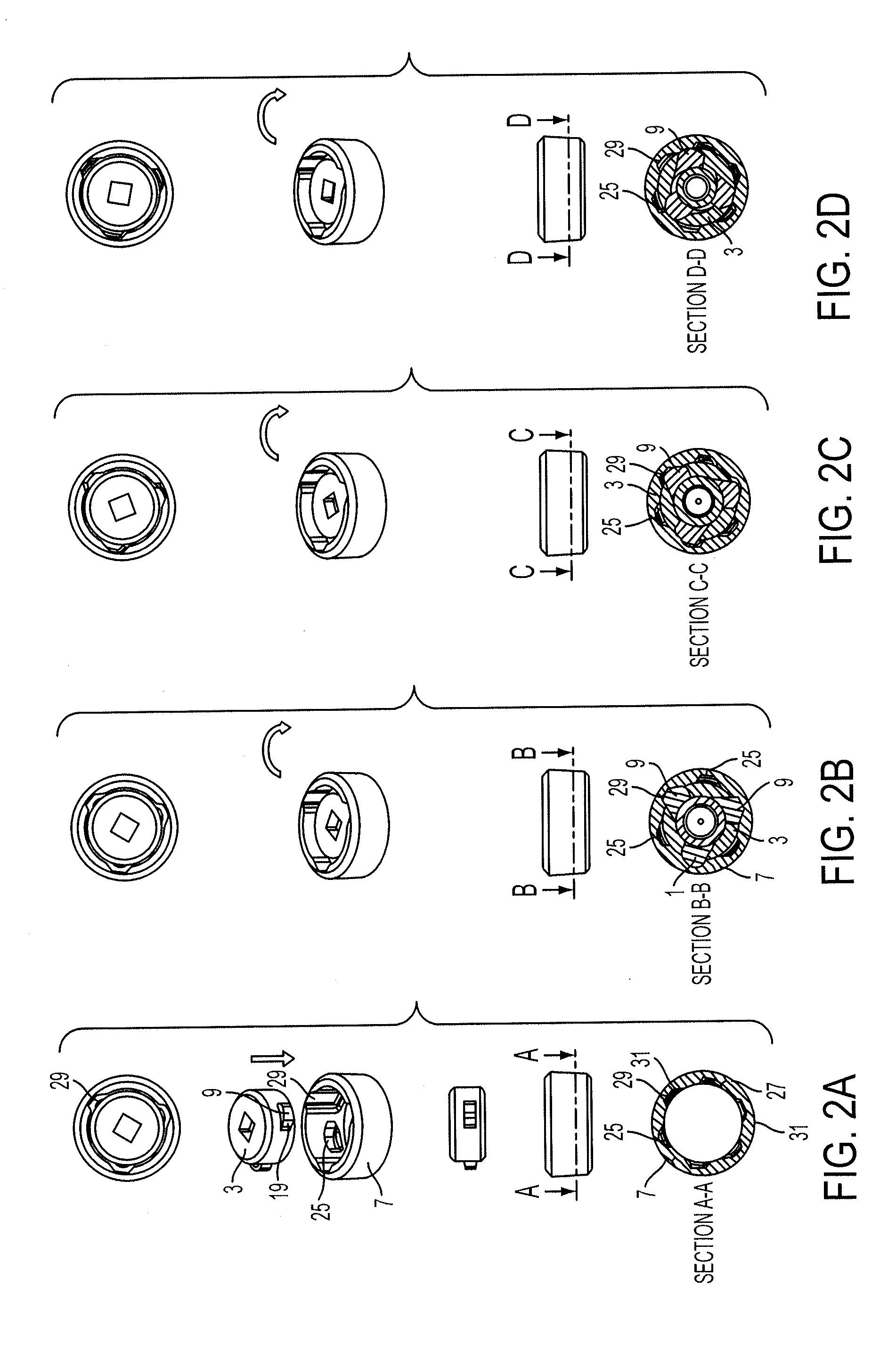
[0057]In the illustrative form, the locking element 3 has a body 4 which is generally cylindrical having an axis CL which forms a first locking axis of the body 4 and about which the locking element is arranged to rotate in use. The locking element 3, as illustrated, also has three tabs 9 movable between an extended position and a retracted position relative to the first locking axis. The locking surface 5 has three retaining elements 11, which when engaged with the respective tabs 9, prevent relative movement between t...

second embodiment

[0082]the locking element will now be described with reference to FIGS. 3 to 5C. The locking element 103 has tabs 109, that has a movement axis extending radially from the first locking axis of the body 104 of the locking element 103. FIGS. 5A to 5C illustrate various positions of the tabs 109 as they move radially between their extended and retracted positions.

third embodiment

[0083]the locking element will now be described with reference to FIGS. 6 to 8C. The locking element 203 has tabs 209, that are pivotally attached by pivots 210 to the body 204. The pivots 210 allow the tabs to swing outwardly between an extended position and a retracted position. A resilient element 221 is provided for each tab 209 to bias the tabs to the extended position. FIGS. 8A to 8C illustrate various positions of the tabs 209 from an extended position to a retracted position.

[0084]A further embodiment of the locking element (not shown) may have tabs with additional camming surfaces on the tabs. In one form, the additional camming surfaces may allow the lock assembly to be locked and unlocked in both directions (i.e. clockwise and anti-clockwise when viewed from the top view). A further alternative is to have camming surfaces on the underside of the tabs (i.e. the face when viewing towards the bottom surface 14 of the body), thereby allowing the lock element 3 to be push fit ...


PUM


Abstract

A lock assembly comprising a locking element having; a body having a first locking axis; at least one tab movable relative to the body, the tab movable between a retracted position and an extended position relative to the first locking axis; a locking surface having at least one retaining element; wherein the lock assembly is operative to adopt a locked condition where the at least one tab engages with a respective one of the at least one retaining element to prevent relative movement between the locking element and the locking surface in at least one direction of the first locking axis.

Description

REFERENCE TO RELATED APPLICATIONS[0001]This application is a continuation of International Application No. PCT / AU2012 / 000618, filed Jun. 1, 2012, which claims the priority of Australian Application No. 2011902169, filed Jun. 2, 2011, the entire contents of which are incorporated herein by reference.FIELD OF THE INVENTION[0002]The present disclosure generally relates to lock assemblies, components for lock assemblies and lock systems which include a lock assembly and / or lock components. The locks of the disclosure have particular application for use in land based excavating equipment to retain a member such as a wear member or rigging to excavating equipment and the disclosure is herein disclosed in that context . However, the locks of the disclosure have broader application, for example for waterborne excavators, such as dredgers, or securing liners to mineral processing equipment and accordingly it is to be appreciated that the disclosure is not limited to that application.BACKGROU...

Claims


Application Information

Patent Timeline
IPC IPC(8): E02F9/28
CPCE02F9/2883E02F3/58E02F9/2841F16G15/06F16B2200/73
Inventor MARTINELLI, JOEL NELIOLIZDENIS, CHADLUNN, JASON
Owner BRADKEN RESOURCES
Why Eureka
Try Eureka