Method for determining location of wireless devices

a wireless device and location technology, applied in the direction of direction finders, location information based services, instruments, etc., can solve the problems of indoors methods that do not work well

Active Publication Date: 2014-07-03
CSR TECH INC
View PDF8 Cites 145 Cited by
  • Summary
  • Abstract
  • Description
  • Claims
  • Application Information

AI Technical Summary

Problems solved by technology

These methods, however do not work well indoors due to the limited availability of GPS satellite signals and mobile telephone signals.

Method used


Image

  • Method for determining location of wireless devices
  • Method for determining location of wireless devices
  • Method for determining location of wireless devices

Examples


Embodiment Construction

[0008]Increasingly, indoor locations such as malls, hotels, offices and train stations, provide multiple WiFi access points that, as long they operate according to an appropriate protocol, can be used for to determine the location of a WiFi capable device with high accuracy.

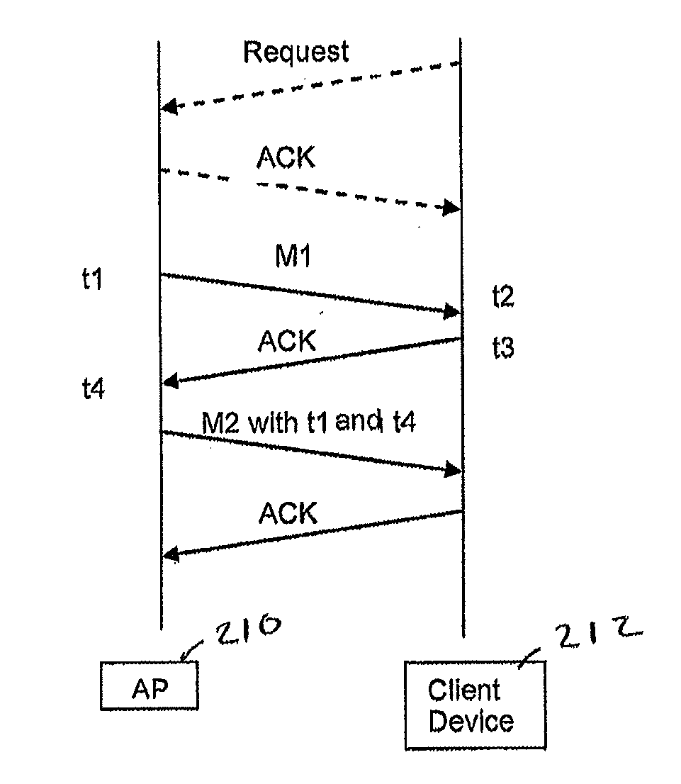
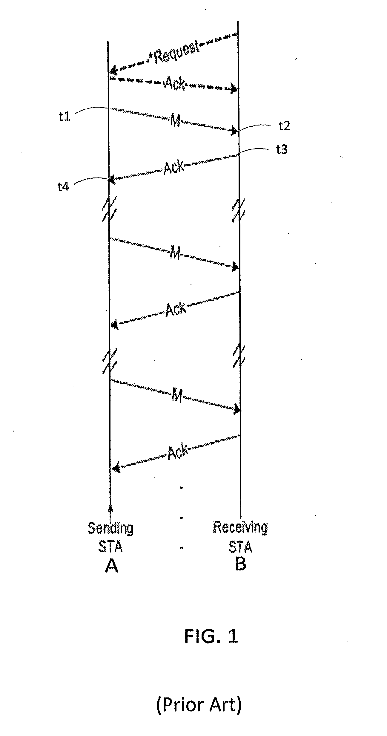
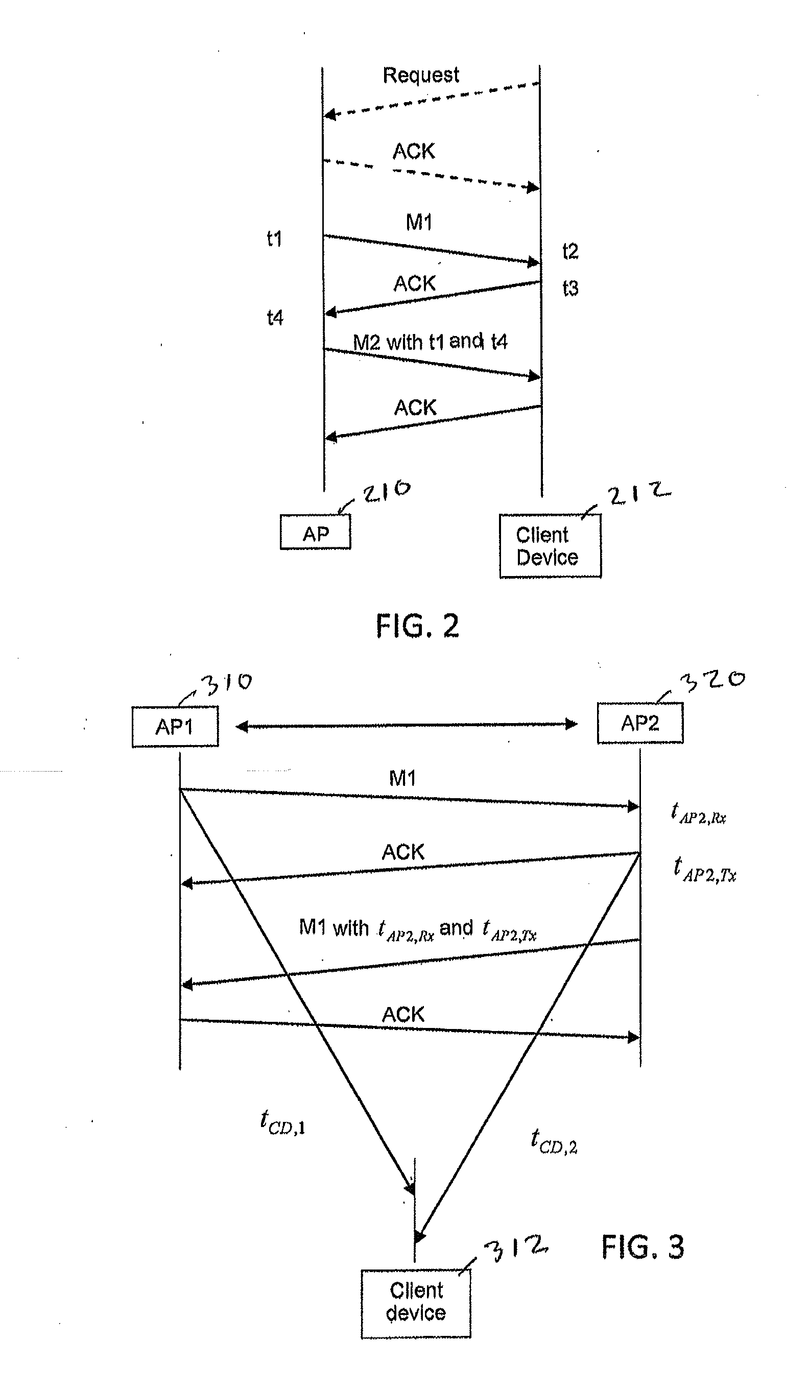
[0009]Proposed methods for performing WiFi location include Round Trip Time (RTT) measurements and other methods using Time of Arrival (ToA) and Time of Departure (ToD) measurements. The materials that follow disclose: 1) a method to compute location using RTT which reduces the burden on the client, 2) a first receive-only location method which reduces communications overhead and may reduce power consumption by the client device and 3) a second receive only method for use in Wi-Fi systems employing beamforming. Although the invention is described in terms of a WiFi network, it is contemplated that it may be used for other wireless technologies including, without limitation, LTE, 3GPP, Bluetooth®, Zigbee® and WiGi...


PUM


Abstract

To determine a location of a client device in a wireless network having at least first and second network devices, with known locations, one of the network devices transmits a message to the other network device and the other network device responds with an acknowledgement message. A client device receives the message and the acknowledgement message as well as respective times indicating actual times at which the message and the acknowledgement message were processed by one of the first and second network devices. The client device determines its location based on the times at which it received the message and the acknowledgement message and the difference between the actual processing times. This location may be refined by determining an angle between the client device and at least one of the network devices having multiple antennas and being configured for steered beam communications.

Description

BACKGROUND OF THE INVENTION[0001]Determining the location of a portable device, such as a wireless telephone typically uses GPS or trilateration of mobile telephone signals broadcast from cell towers at known positions. These methods, however do not work well indoors due to the limited availability of GPS satellite signals and mobile telephone signals. Indoor positioning is important for determining the location of a portable device in buildings such as malls, hotels, offices, train stations etc.SUMMARY[0002]A method for determining a location of a client device in a wireless network having at least first and second network devices, with known locations, includes transmitting a message from the first network device to the second network device, receiving the message at the second network device and transmitting an acknowledgement message. The method further includes transmitting, at least one further message from the second network device to the first network device, this message in...

Claims


Application Information

Patent Timeline
Patent Type & Authority Applications(United States)
IPC IPC(8): H04W4/02
CPCH04W4/023G01S5/08G01S5/14G01S11/02H04W4/025H04W64/00H04W4/02G01S5/10G01S1/20G01S3/46
Inventor KAKANI, NAVEEN KUMARTARLOW, BENLINDSKOG, ERIKBANERJEA, RAJAWAN, HONGBLAIR, IAN CHARLES
Owner CSR TECH INC
Why Eureka
Try Eureka