Power tool having improved tool accessory securing mechanism

a technology of tool accessories and securing mechanisms, applied in the field of power tools, can solve the problems of many types of tools (tool accessories) having pointed or sharp edges

Active Publication Date: 2014-07-10
MAKITA CORP
View PDF11 Cites 27 Cited by
  • Summary
  • Abstract
  • Description
  • Claims
  • Application Information

AI Technical Summary

Benefits of technology

[0006]According to some embodiments of the present disclosure, in order to remove or detach the tool, the grasping part of the operating mechanism is moved in the direction away from the tool. This makes it possible to keep the grasping part and the hand of the operator that is grasping the grasping part away from the tool, thereby reducing the possibility that the operator's hand will accidently come into contact with the sharp tool while the tool is being released. Namely, techniques for improving the operating mechanism, e.g., the safety thereof, are disclosed herein.
[0019]According to such an embodiment, a configuration may be adopted such that the grasping part is pivotable in two different directions. This makes it possible to more reliably differentiate between (i) the movement of the grasping part in order to switch between the first mode and the second mode and (ii) the movement of the grasping part to the third position in order to store the grasping part.

Problems solved by technology

However, many types of tools (tool accessories) have pointed or sharp edges.
Therefore, if the user's hand slips while shifting the level to the release position, it is possible that the user's hand will accidently come into contact with the sharp tool, thereby causing injury.

Method used


Image

  • Power tool having improved tool accessory securing mechanism
  • Power tool having improved tool accessory securing mechanism
  • Power tool having improved tool accessory securing mechanism

Examples


first embodiment

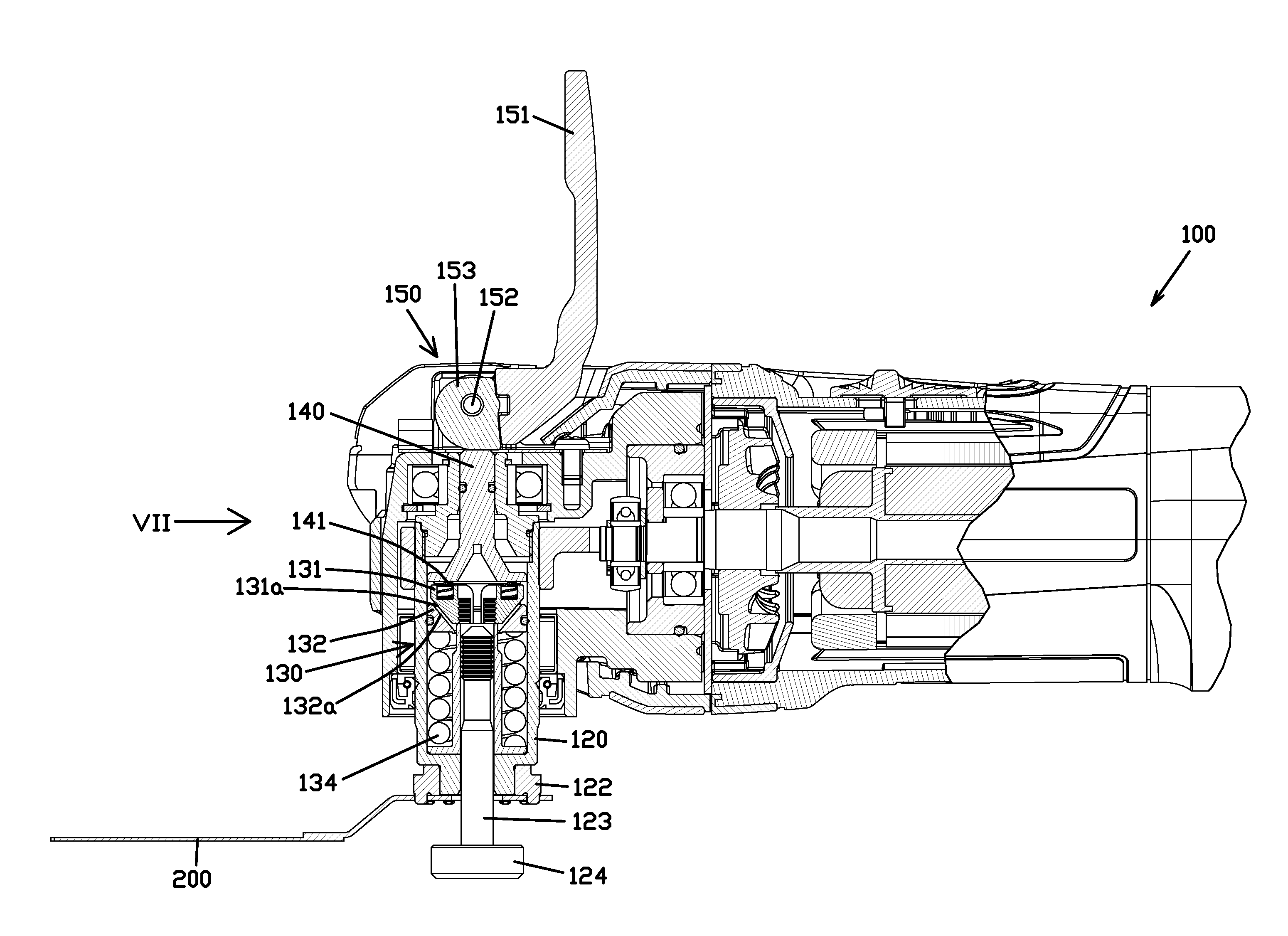
[0033]A first embodiment of the present disclosure will now be explained in detail, referencing FIG. 1 through FIG. 7. The explanation below is directed to a power tool in the form of a so-called oscillating multi-tool.

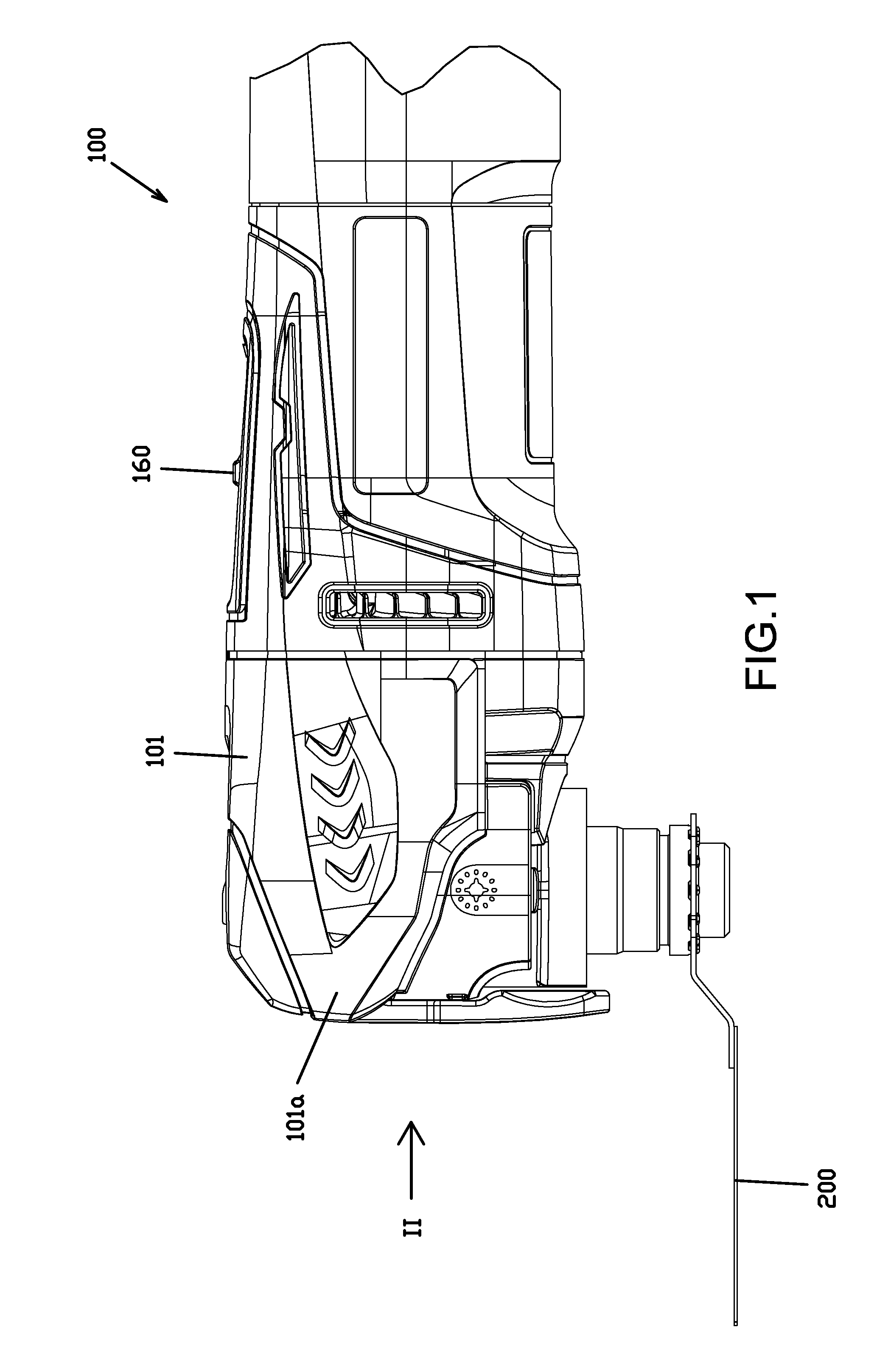
[0034]As shown in FIG. 1, an oscillating multi-tool 100 is type of a power tool, to which various tools (e.g., tool accessories or tool attachments), such as (without limitation) saw blades, scrapers, scraper plates, files, sand paper pads and polishing pads, can be selectively (interchangeably) attached. The multi-tool causes the attached tool to oscillate about a small pivot angle or range (e.g. 3.2°) in order to cut, grind, or otherwise act on (process) a work piece. The embodiment below uses a plunge cut saw blade 200 as one representative example of a detachable (clampable) tool, tool accessory or tool attachment (tip tool) according to the present teachings.

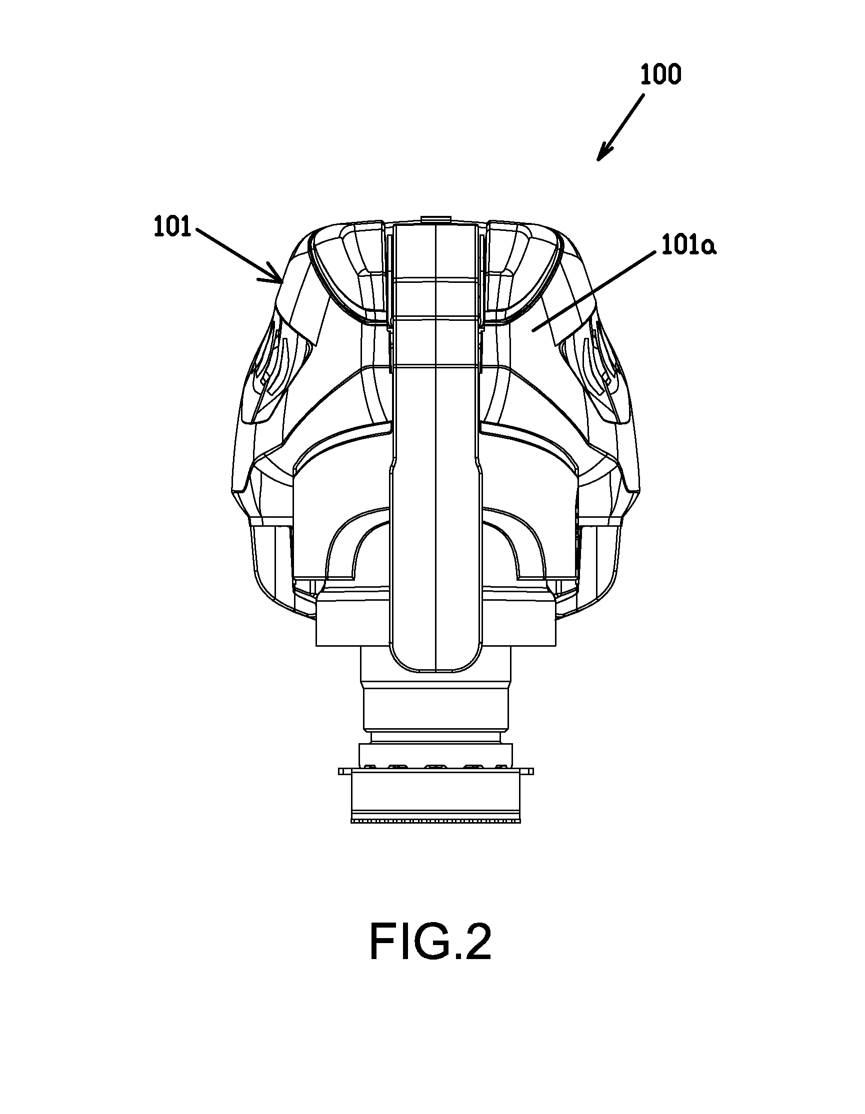
[0035]As shown in FIG. 1 and FIG. 2, the outer contour or shape of the multi-tool 100 is formed by a main ...

second embodiment

[0054]Next, a second embodiment of the present disclosure will be explained with reference to FIG. 8 through FIG. 10. The second embodiment differs from the first embodiment principally in the configuration of cam lever mechanism 250. Consequently, constituent elements that are the same as those in the first embodiment have been assigned the same reference numbers, and explanations thereof are therefore omitted where they would be merely repetitive. That is, the description of the first embodiment is incorporated by reference into the description of the second embodiment to the extent that identical or substantially similar elements, functions, configurations, etc. are present in the second embodiment.

[0055]As shown in FIG. 8, the cam lever mechanism 250 principally comprises a lever part (pivotable handle) 251, a (first) pivot axle 252, an eccentric part 253, and a (second) pivot axle 254.

[0056]The lever part 251 is pivotally supported by the (second) pivot axle 254 and is thereby ...

third embodiment

[0060]Next, a third embodiment of the present disclosure will be explained with reference to FIG. 11 through FIG. 13. The third embodiment differs from the first embodiment principally in the configuration of cam lever mechanism 350. Consequently, constituent elements that are the same as those in the first embodiment have been assigned the same reference numbers, and explanations thereof are therefore omitted where they would be merely repetitive. That is, the description of the first and second embodiments is incorporated by reference into the description of the third embodiment to the extent that identical or substantially similar elements, functions, configurations, etc. are present in the third embodiment.

[0061]As shown in FIG. 11, the cam lever mechanism 350 principally comprises a lever part (pivotable handle) 351, a pivot axle 352, and an eccentric part 353.

[0062]The lever part 351 comprises an eccentric part contact part 351a and a slide guide 351b. The eccentric part conta...


PUM


Abstract

A power tool includes a clamp shaft for clamping a tool accessory to the power tool and a clamp shaft holding mechanism for selectively locking the clamp shaft to hold the clamp shaft in a position that secures the tool accessory on the power tool. The power tool also includes a lever for shifting the clamp shaft holding mechanism between clamped and unclamped states. The lever is configured such that when an operator grasps the lever and moves it toward a position for releasing the tool accessory, the lever and the operator's hand move away from the tool accessory.

Description

CROSS-REFERENCE[0001]This application claims priority to Japanese patent application no. 2013-000690 filed on Jan. 7, 2013, the contents of which are fully incorporated herein by reference.TECHNICAL FIELD[0002]The present disclosure is generally directed to a power tool (work tool), e.g., an oscillating multi-tool, that drives an interposingly held (clamped) tool accessory (tip tool), and, in certain aspects, generally relates to a power tool having an improved clamping arrangement for securing the tool accessory to a pivotable or rotatable spindle.BACKGROUND ART[0003]PCT International Publication No. WO2005 / 102605 (see also US2007 / 060030) describes a hand-held power tool that drives a detachable tool (tool accessory) interposed (clamped) between and held by a work spindle and a fastening element. This power tool is configured such that the fastening element is movable relative to the working spindle between a clamped position and an open or release position. When the fastening elem...

Claims


Application Information

Patent Timeline
Patent Type & Authority Applications(United States)
IPC IPC(8): B23Q3/14
CPCB23Q3/14B23D61/006B24B23/04B24B45/006B27B5/32B27B19/006Y10T279/34Y10T279/33B23B31/10
Inventor KAWAKAMI, TAKAHIRONAKAMURA, SHINNAKAHAMA, MASATOSHI
Owner MAKITA CORP
Why Eureka
Try Eureka