Abnormality detection system for rotation angle sensor

a technology of rotation angle and detection system, which is applied in the direction of dynamo-electric components, instruments, and converting sensor output electrical/magnetically, to achieve the effect of improving the ability to detect abnormalities

Active Publication Date: 2014-07-10
JTEKT CORP
View PDF3 Cites 29 Cited by
  • Summary
  • Abstract
  • Description
  • Claims
  • Application Information

AI Technical Summary

Benefits of technology

[0009]One object of the invention is to provide an abnormality detection system for a rotation angle sensor, having an improved capability of detecting an abnormality of a magnetic sensor.
[0015]In addition, the following advantageous effect is obtained. An abnormality of the rotation angle sensor is detected based on the comparison among the temperatures correlated with the amplitude instead of the comparison based on the amplitude that is easily influenced by the temperature (comparison among the values of the sums of squares). Therefore, the result of detection of presence or absence of the abnormality is less likely to be influenced by the temperature. Because the result of detection of the presence or absence of an abnormality is less likely to be influenced by the temperature, the capability of detecting an abnormality in the rotation angle sensor is improved.
[0018]With this configuration, it is possible to appropriately execute detection of an abnormality during the backup control without the influence of the temperature. In the abnormality detection system for a rotation angle sensor, the rotary shaft may be a rotary shaft of a motor. In this case, the temperature sensor may be provided to protect a drive circuit of the motor from overheating.
[0020]With the configuration described above, it is possible to improve the capability of detecting an abnormality of the magnetic sensor.

Problems solved by technology

However, when the presence or absence of an abnormality of the magnetic sensor is detected on the basis of the value of the sum of squares of the cosine component and the sine component, there is the following problem.

Method used


Image

  • Abnormality detection system for rotation angle sensor
  • Abnormality detection system for rotation angle sensor
  • Abnormality detection system for rotation angle sensor

Examples


Embodiment Construction

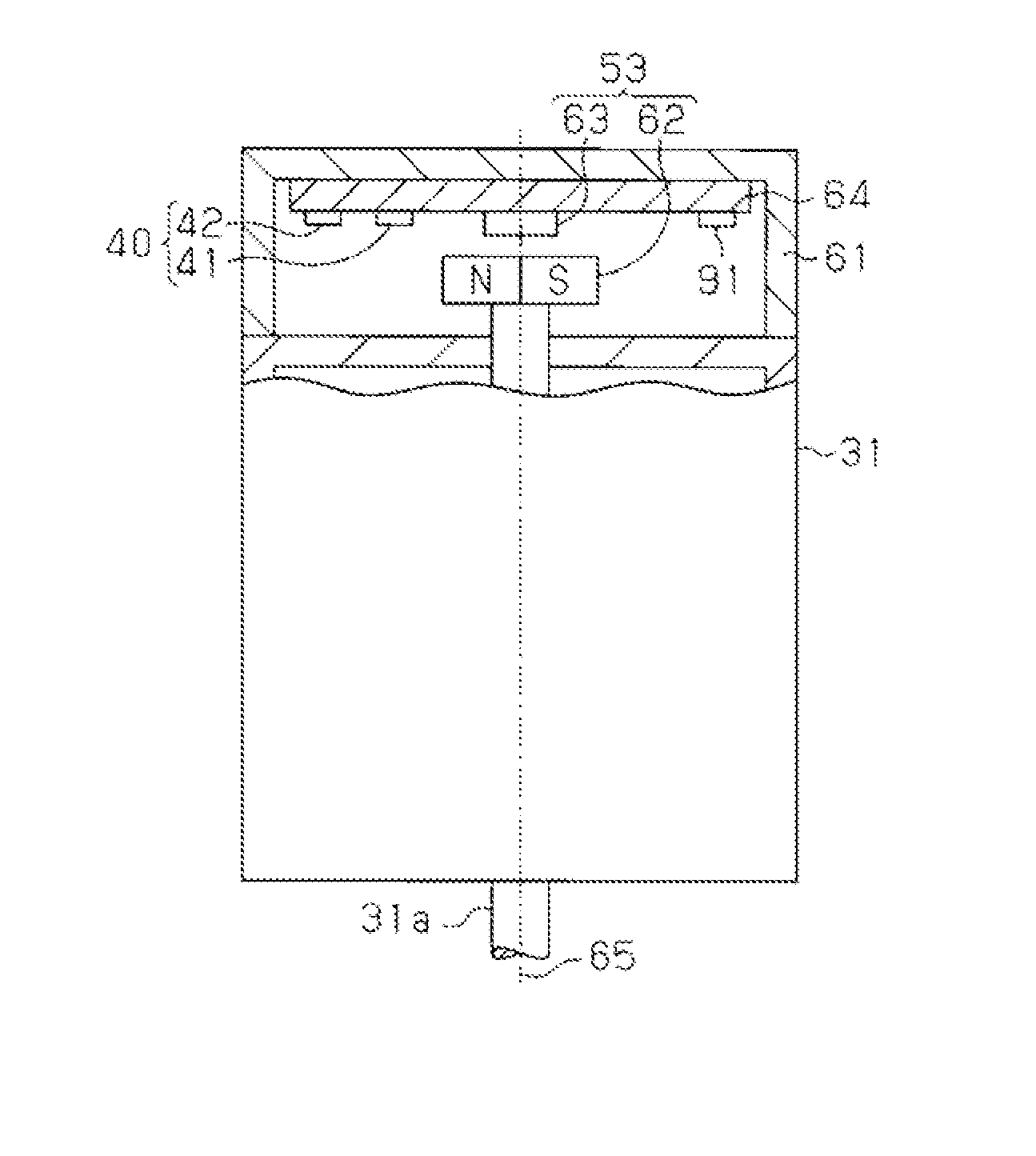
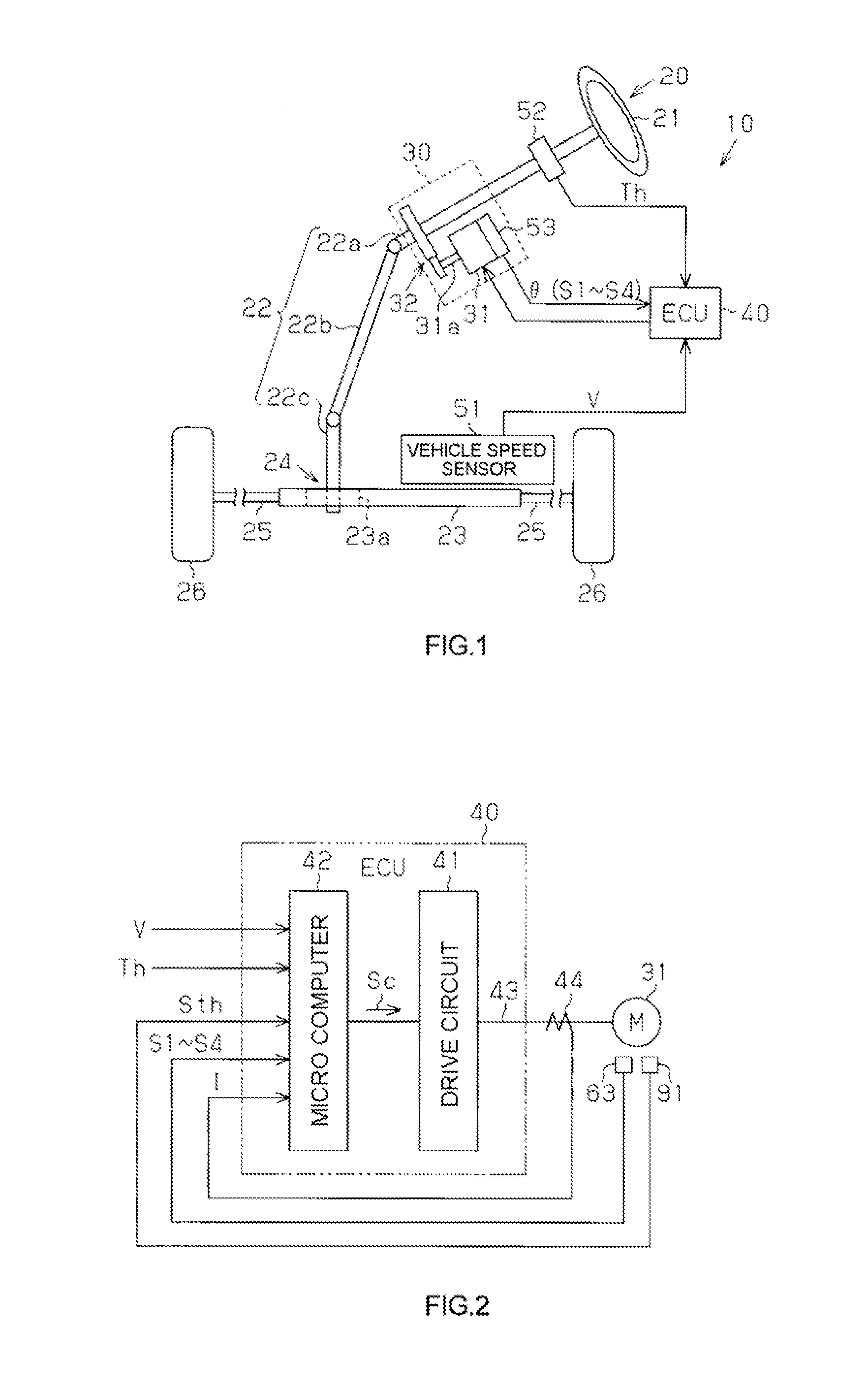
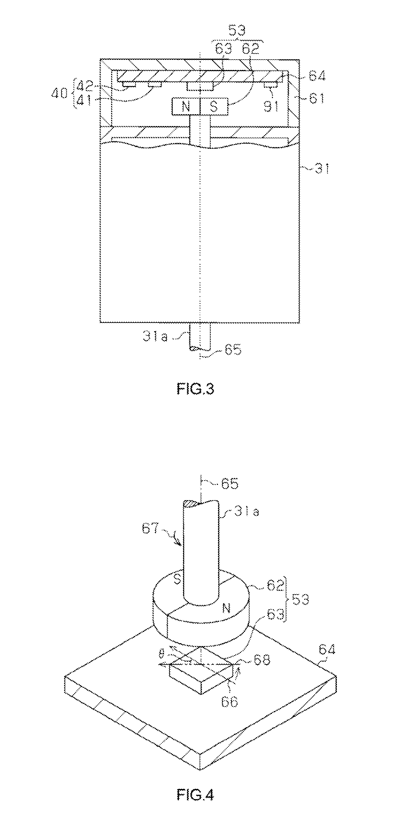
[0028]Hereinafter, description will be provided on an embodiment in which an abnormality detection system for a rotation angle sensor according to the invention is applied to an electric power steering system. As illustrated in FIG. 1, an electric power steering system (EPS) 10 includes a steering mechanism 20 that steers steered wheels on the basis of a driver's steering operation, a steering assist mechanism 30 that assists the driver's steering operation, and an electronic control unit (ECU) 40 that controls the operation of the steering assist mechanism 30.

[0029]The steering mechanism 20 includes a steering wheel 21 that is operated by the driver, and a steering shaft 22 that rotates together with the steering wheel 21. The steering shaft 22 includes a column shaft 22a connected to the center of the steering wheel 21, an intermediate shaft 22b connected to the lower end of the column shaft 22a, and a pinion shaft 22c connected to the lower end of the intermediate shaft 22b. The ...


PUM


Abstract

In an abnormality detection system for a rotation angle sensor, a fact that an abnormality has occurred in one of sine signals (S1, S2) or in one of cosine signals (S3, S4) is detected based on a sum of the electrical signals (S1, S2), and a sum of the electrical signals (S3, S4) (first detection result). A fact that an abnormality has occurred in one of the positive sine and cosine signals (S1, S3) or in one of the negative sine and cosine signals (S2, S4) by comparing a first temperature computed using a correlation between an amplitude and a temperature and based on the electrical signals (S1, S3), a second temperature computed using a correlation between the amplitude and a temperature and based on the electrical signals (S2, S4), and a third temperature detected by a temperature sensor with each other (second detection result). A microcomputer identifies which of the electrical signals is abnormal by comparing the first and second detection results with each other.

Description

INCORPORATION BY REFERENCE[0001]The disclosure of Japanese Patent Application No. 2013-001077 filed on Jan. 8, 2013 including the specification, drawings and abstract, is incorporated herein by reference in its entirety.BACKGROUND OF THE INVENTION[0002]1. Field of the Invention[0003]The invention relates to an abnormality detection system for a rotation angle sensor.[0004]2. Description of the Related Art[0005]As described in, for example, Japanese Patent Application Publication No. 2011-95094 (JP 2011-95094 A) (FIG. 14), using a magnetic sensor as a rotation angle sensor that detects a rotation angle of a rotary shaft of a motor or the like has been conventionally known. The magnetic sensor has two bridge circuits each including four magnetoresistive elements. The two bridge circuits generate electrical signals based on the direction of a magnetic field generated by a magnet disposed on the rotary shaft. The first bridge circuit generates two electrical signals corresponding to a c...

Claims


Application Information

Patent Timeline
Patent Type & Authority Applications(United States)
IPC IPC(8): G01R35/00H02K11/00
CPCG01R35/00H02K11/0047H02K11/0021G01D3/08H02K11/215H02K11/25G01D5/24485G01D5/12G01R33/02G01R33/07
Inventor KITAMOTO, HIROSHI
Owner JTEKT CORP
Why Eureka
Try Eureka