Door structure for floating flap gate

a technology of flap gate and door structure, which is applied in the field of door structure in a floating flap gate, can solve the problems of inability to maintain the raised state and the inability of the lock gate to float, and achieve the effect of light weigh

Inactive Publication Date: 2014-07-10
HITACHI ZOSEN CORP
View PDF15 Cites 8 Cited by
  • Summary
  • Abstract
  • Description
  • Claims
  • Application Information

AI Technical Summary

Benefits of technology

[0010]The present invention can be designed to be light in weight, because the door body is formed from a hard polyurethane foam in the form of a sheet. Moreover, the door body can be raised without a sudden decrease in buoyancy, even if the hard polyurethane foam in the form of a sheet is damaged by a wheel load of a vehicle traveling above the do

Problems solved by technology

However, in the tide gate apparatus of the lock gate according to Patent Reference 1, if the lock gate is damaged by a wheel load of a vehicle traveling above the lock gate when it is in a lowered state, there is a problem that the lock gate cannot float when water flows into an inner part of the loc

Method used


Image

  • Door structure for floating flap gate
  • Door structure for floating flap gate
  • Door structure for floating flap gate

Examples


examples

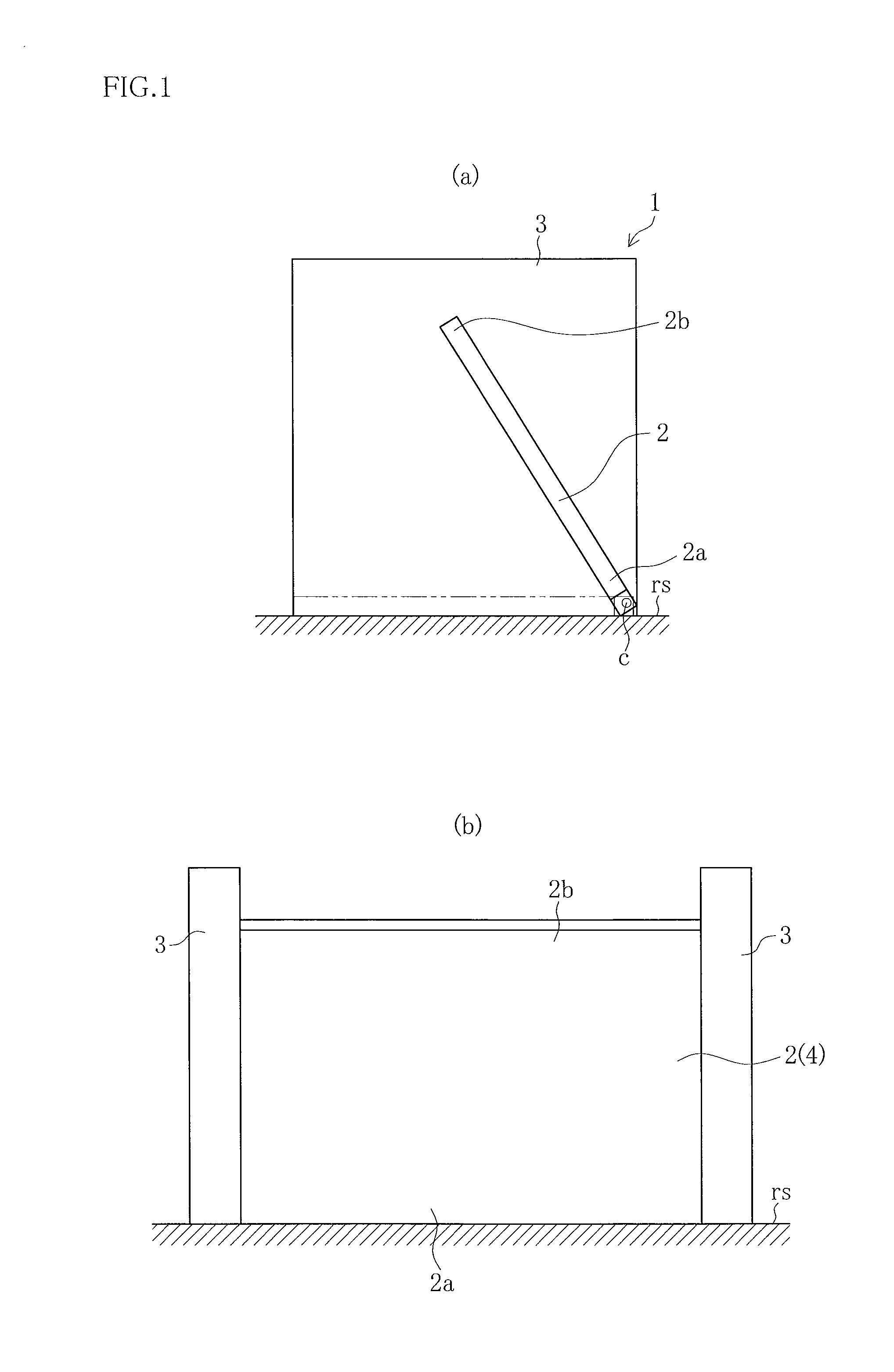
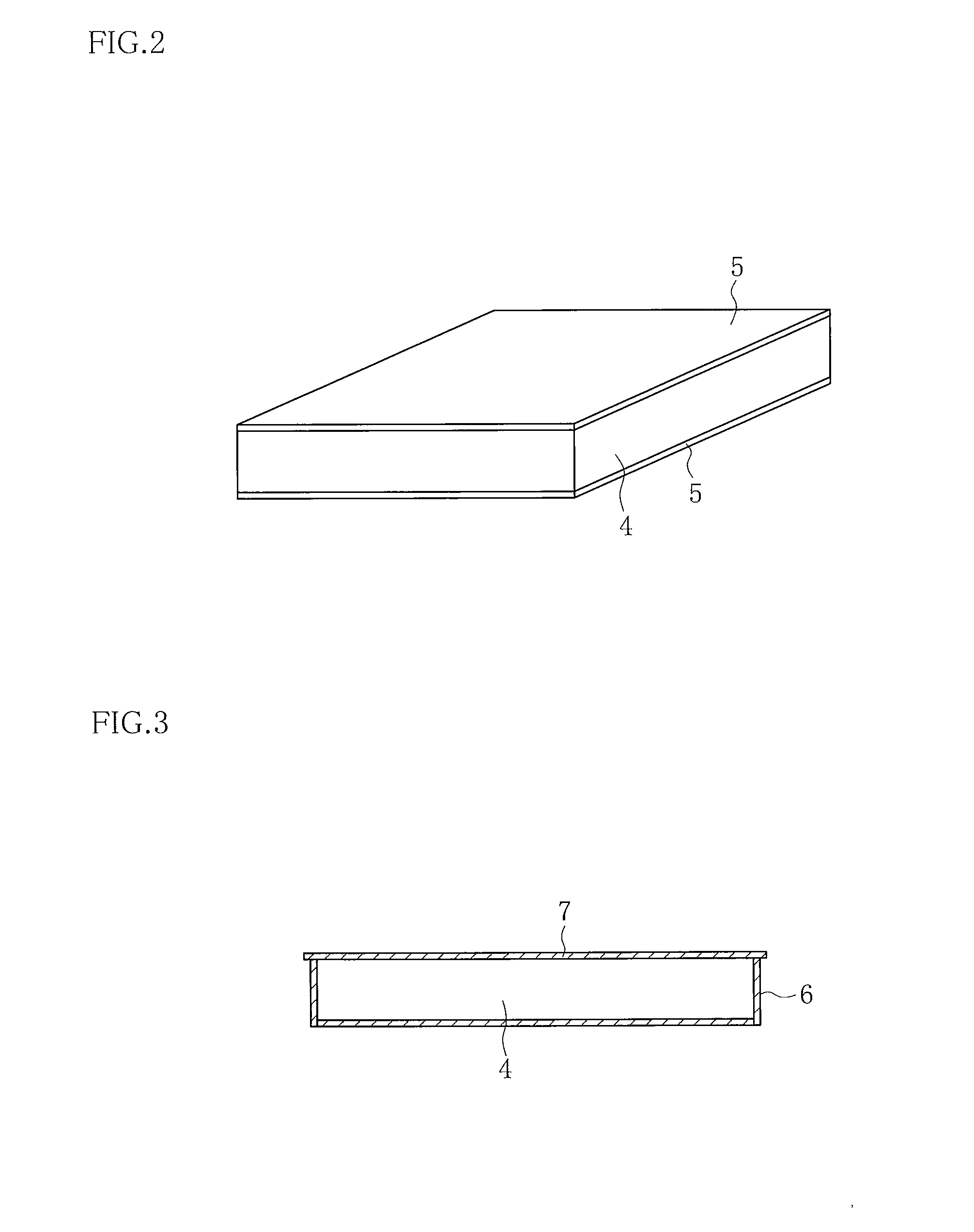
[0019]The present invention is described below using FIG. 1 to FIG. 7.

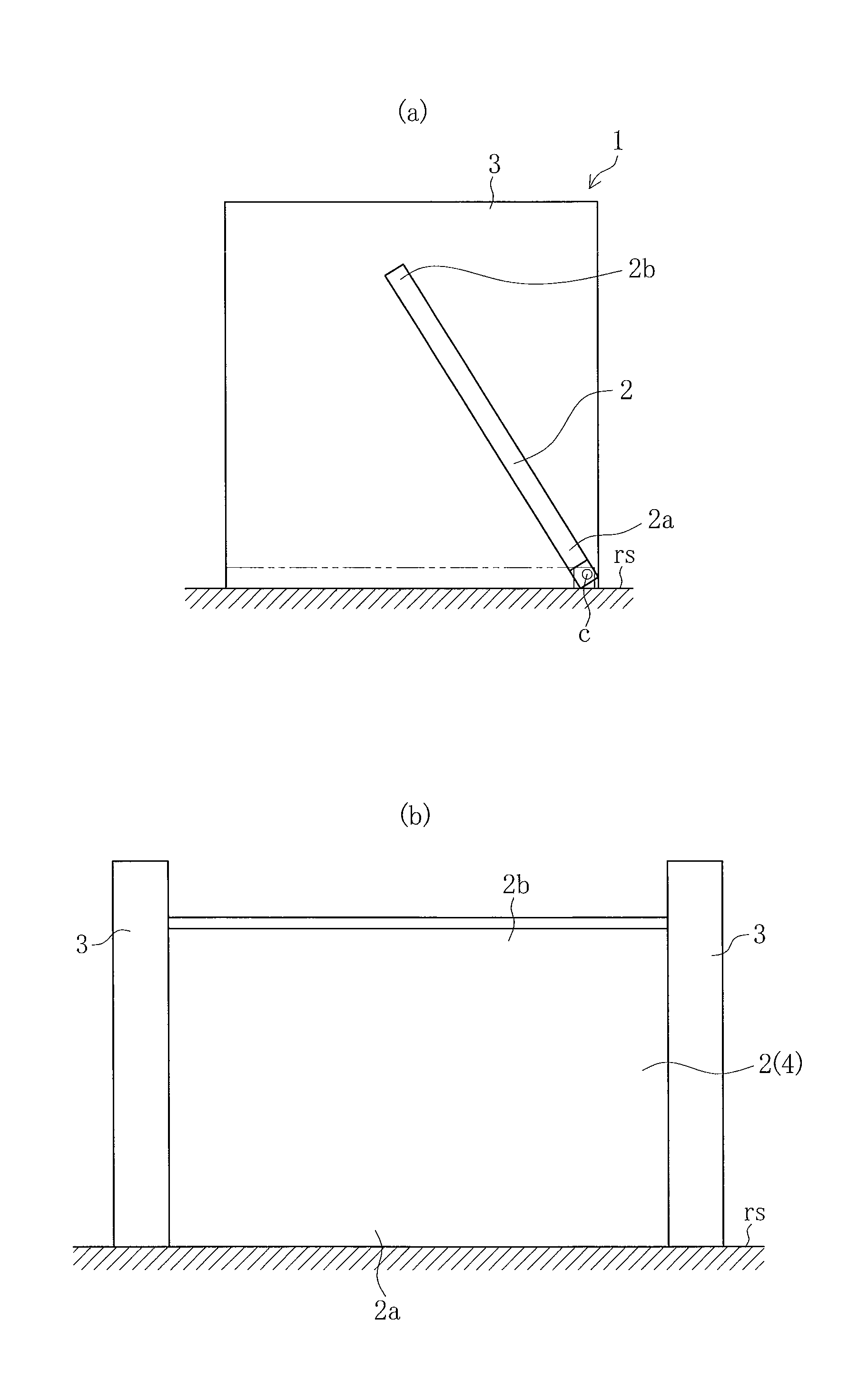
[0020]FIGS. 1 (a) and (b) are schematic structural drawings of a floating flap gate having the door body structure according to the present invention.

[0021]In FIG. 1, Reference Numeral 1 is a floating flap gate according to the present invention which is disposed on a channel surface rs at an opening in a seawall, for example, and is formed such that when a door body 2 rises, both sides of the door body 2 and a side door bumper 3 provided at the opening of the seawall are kept in a water-tight state.

[0022]When a water tries to flow from an ocean (or from a river) into a public space, for example, the floating flap gate 1 uses the pressure of the water to swing a forward end 2b of the door body 2 upwards around a base end 2a as a center of rotation c, to water-tightly block the opening.

[0023]The floating flap gate 1 according to the present invention comprises a door body 2 with a forward end 2b which swings upward...


PUM


Abstract

To make it possible to raise a door body even if it is damaged by an impact of vehicle traffic or falling objects when it is in a lowered state, and to keep the door body in a raised state even if it is damaged by a water pressure of a tsunami or a high tide when it is in a raised state. A door body 2 of a floating flap gate 1 is disposed at an opening or at an access way. When water flows in, a forward end 2b of which swings upwards, in a direction in which the water flows in and within a plane in a height direction, around a base end 2a thereof which serves as a center of rotation, to block the opening or the access way. The door body 2 is formed from a hard polyurethane foam 4 in the form of a sheet.

Description

TECHNICAL FIELD[0001]The present invention relates to a structure of a door in a floating flap gate which blocks an opening by causing the door body to rise to prevent a rising water from flowing into a public space, for example, at a time of rising water such as a tsunami or a high tide.BACKGROUND ART[0002]In Patent Reference 1, for example, there is disclosed a tide gate apparatus which opens or blocks an opening of a lock gate installed in a seawall or embankment on a seacoast or near a mouth of a river.[0003]In the tide gate apparatus of the lock gate according to Patent Reference 1, a door body is raised to prevent seawater from flowing into an opening of the lock gate, by causing a bypass circuit of a hydraulic device to open, which causes the tide gate to rise due to a water pressure and a buoyancy of the seawater.[0004]However, in the tide gate apparatus of the lock gate according to Patent Reference 1, if the lock gate is damaged by a wheel load of a vehicle traveling above...

Claims


Application Information

Patent Timeline
IPC IPC(8): E02B7/40
CPCE02B7/40E02B3/102E06B2009/007E06B3/38E06B5/003
Inventor ARAI, HIROAKINIIZATO, HIDEYUKIKITAMURA, KOJIOKADA, JUNASHIDA, SATOSHINAKAYASU, KYOUICHIYAMAKAWA, YOSHITO
Owner HITACHI ZOSEN CORP
Why Eureka
Try Eureka