
Pendulum-absorber brake

a technology of pendulum absorber and brake, which is applied in the direction of shock absorber, mechanical apparatus, inertia effect damper, etc., can solve the problems of increased amplitude, material failure, and the pendulum absorber may emit undesirable clunking sound, so as to reduce the torsional stress of the crankshaft, prevent excessive vibration, and prevent excessive vibration.

Inactive Publication Date: 2014-07-17
FORD GLOBAL TECH LLC
View PDF4 Cites 6 Cited by
  • Summary
  • Abstract
  • Description
  • Claims
  • Application Information

AI Technical Summary

Benefits of technology

The patent text explains how to prevent excessive vibration in a crankshaft during rotation. This is achieved by adding counterweights to balance the mass of each crankpin and associated piston, piston rod, and entrained lubricant. These counterweights prevent vibration perpendicular to the crankshaft's rotational axis, but do not address the torsional vibration that occurs around the rotational axis. To suppress this vibration, a pendulum absorber or torsional dampener can be installed on the crankshaft. The pendulum absorber absorbs one or more crankshaft firing-order rigid-body modes by non-rigidly linking a mass to the crankshaft at a predetermined distance from the rotational axis. Its mass and distance from the rotational axis can be adjusted to absorb the rigid-body modes of the crankshaft.

Problems solved by technology

The counterweights may prevent excessive vibration of a crankshaft perpendicular to its rotational axis, but do not address the torsional vibration that may occur about the rotational axis.
When this occurs, the vibration may increase in amplitude, such that the crankshaft is inelastically deformed, causing material failure.
The inventors herein have observed, however, that during periods of very slow crankshaft rotation—such as engine start or stop—a pendulum absorber may emit an undesirable clunking sound when travelling across the clearance.
In other speed / torque regimes, a pendulum absorber may bang against the end-stops at the limits of its intended travel path, also emitting an undesirable sound.
In some cases, premature wear of the crankshaft may occur along with the undesirable sound emission.
Moreover, the caming configuration of Berger may not fully resolve the noise issues observed at low rotational speeds.
In this manner, the greatest braking force becomes available at the lowest rotational speeds—e.g., during engine start or stop—when the pendulum absorber is apt to travel across its clearance, emitting undesirable sound.

Method used


Image

  • Pendulum-absorber brake
  • Pendulum-absorber brake
  • Pendulum-absorber brake

Examples


Embodiment Construction

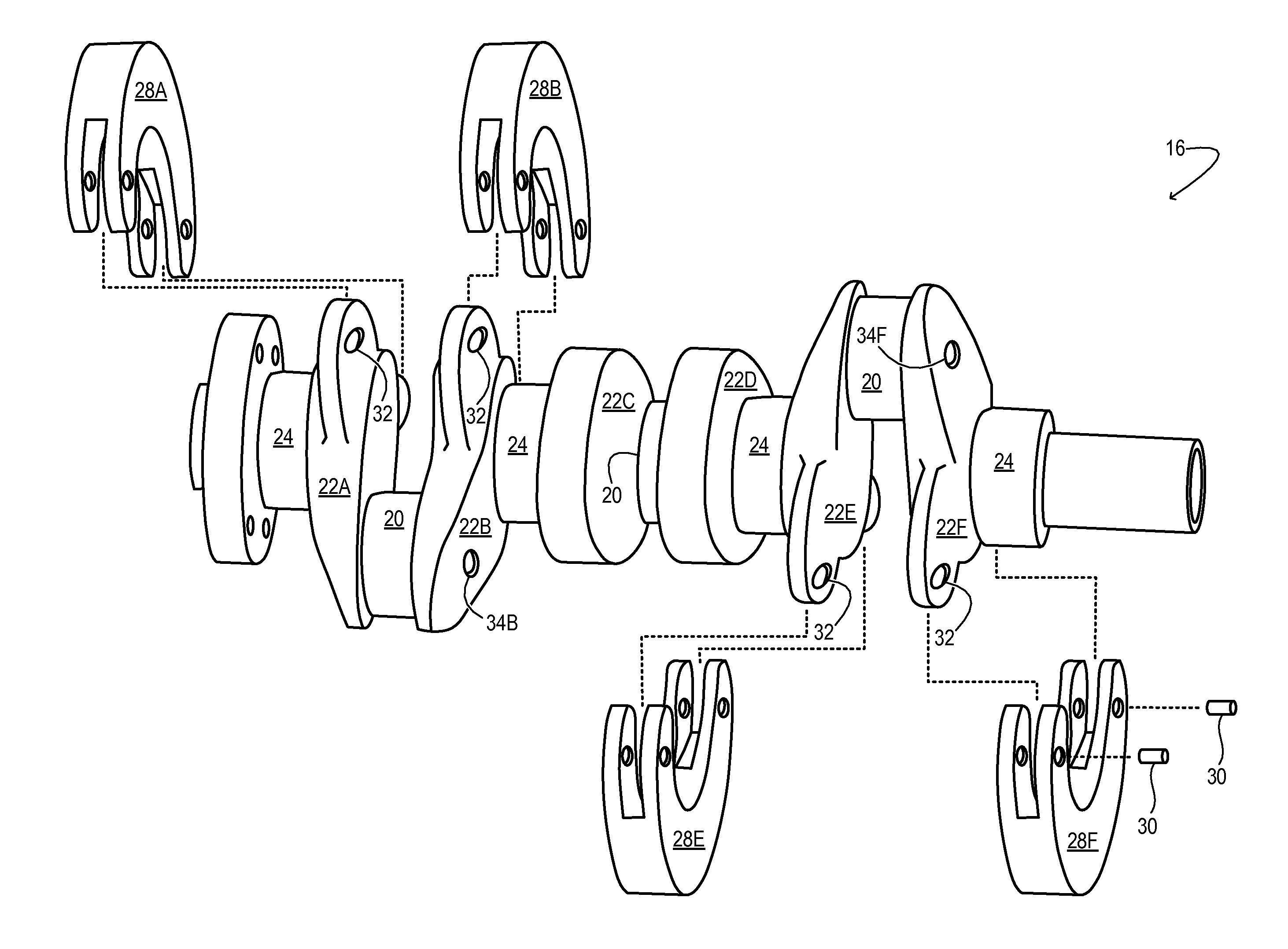
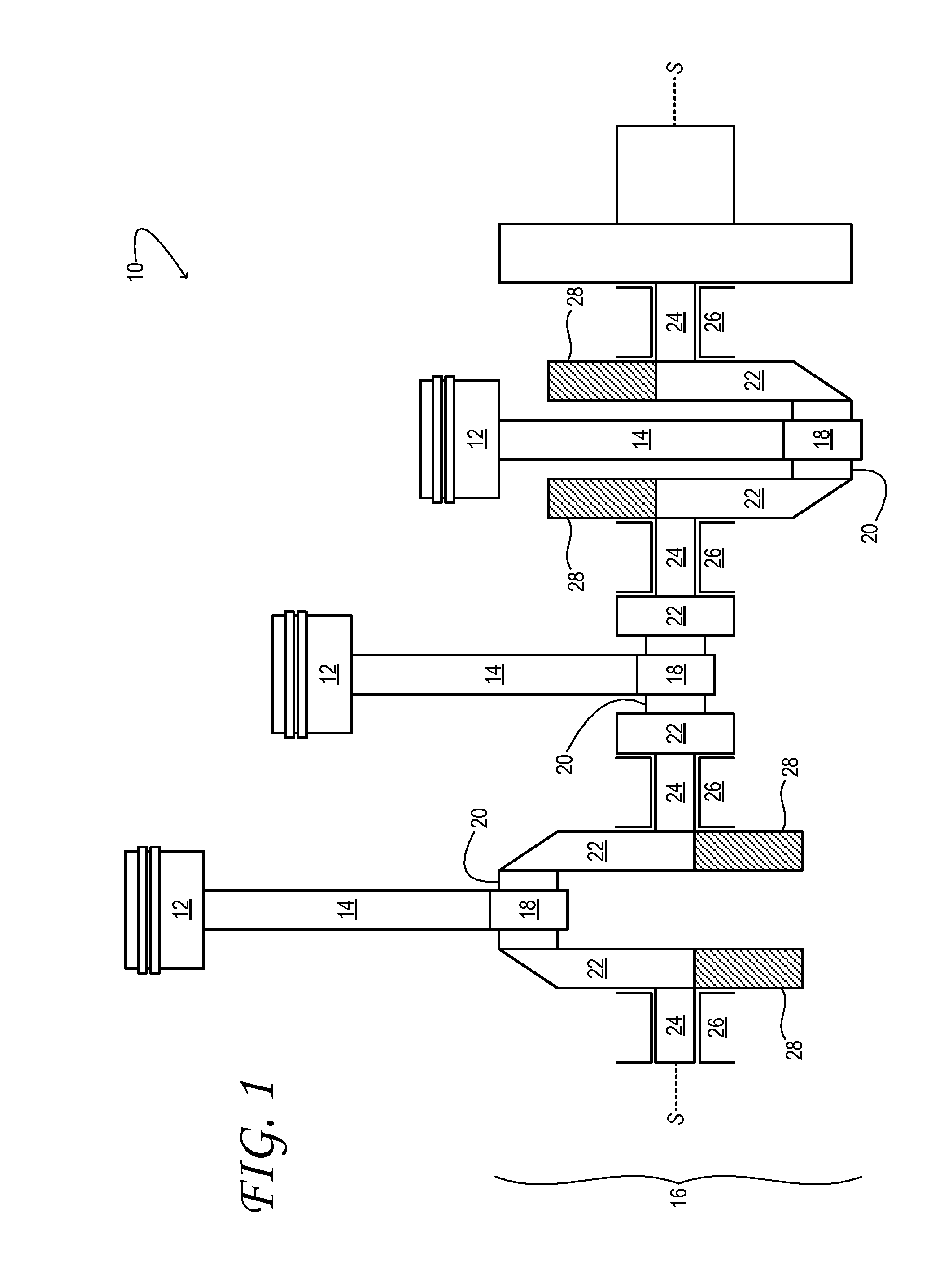
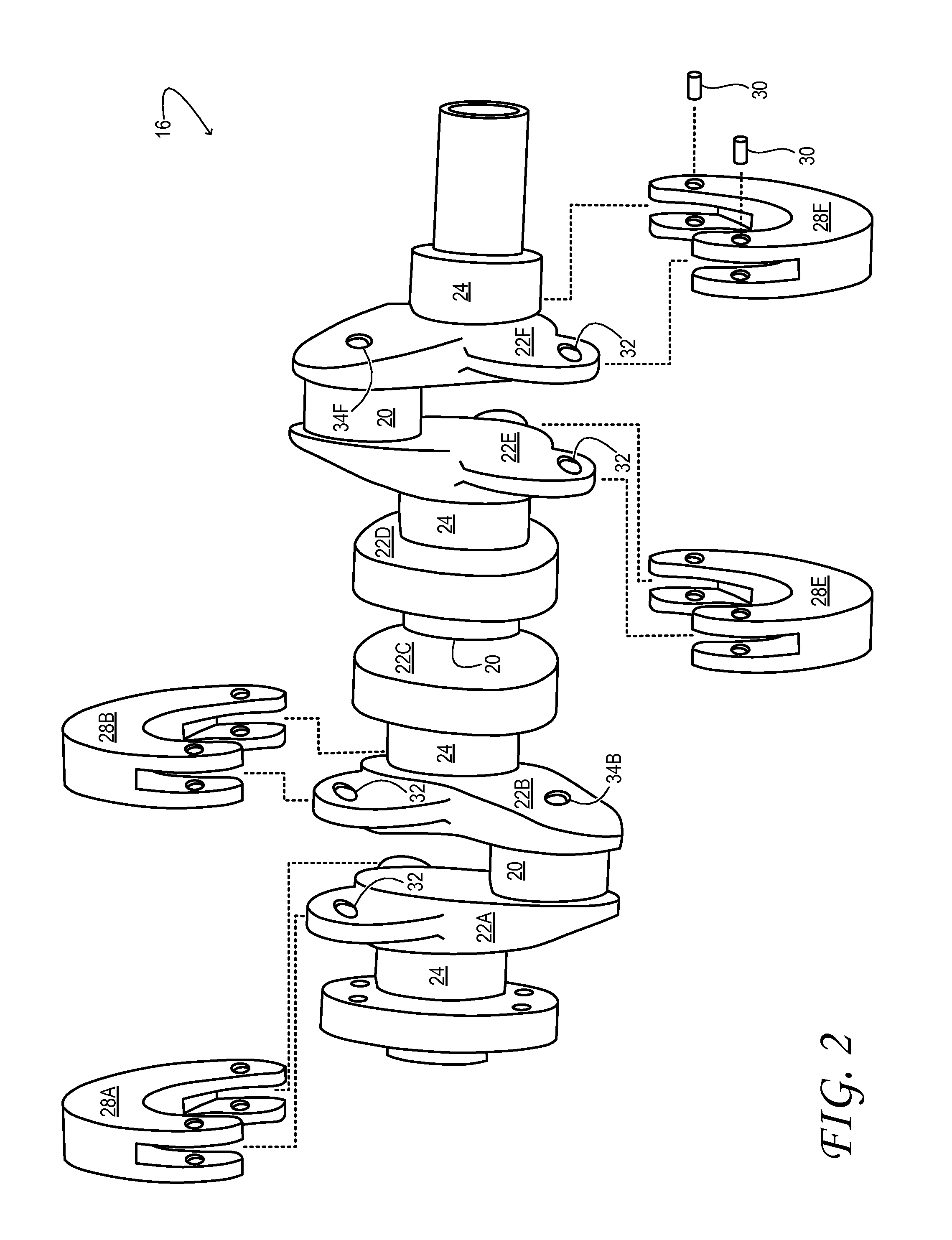
[0017]FIG. 1 schematically shows aspects of an example engine 10 of a motor vehicle. The engine includes a plurality of reciprocating pistons 12. Although three pistons are shown in FIG. 1, this disclosure is equally applicable to engines having more or fewer pistons. Each piston is pivotally coupled to one end of a corresponding piston rod 14. The other end of each piston rod is pivotally coupled to crankshaft 16 through a rod bearing 18. More specifically, a cylindrical crankpin journal—crankpin 20, hereinafter—is rotationally coupled inside each rod bearing. Each crankpin is located between a pair of cheeks 22, and coupled to the same. In the embodiment of FIG. 1, adjacent pairs of cheeks are connected by a plurality main journals 24. The main journals are rotationally coupled inside a corresponding plurality of main bearings 26.

[0018]Crankshaft 16 includes a plurality of pendulum absorbers—pendula 28, hereinafter—which provide torsional-vibration absorption for the crankshaft. E...


PUM


Abstract

A crankshaft comprising a cheek, a torsion-absorbing pendulum pivotally coupled to the cheek, and a rotational speed actuated brake to oppose motion of the pendulum relative to the cheek. The brake is configured to provide greater opposition to the motion at lower rotational speeds than at higher rotational speeds.

Description

TECHNICAL FIELD[0001]This application relates to the field of motor-vehicle engineering, and more particularly, to reducing crankshaft noise and wear in engines having a pendulum-absorber type crankshaft.BACKGROUND AND SUMMARY[0002]In an internal combustion engine, a crankshaft may be used to convert the reciprocating motion of the pistons into rotational motion. The crankshaft may include, offset from its rotational axis, a plurality of crankpins. Each crankpin is coupled through a bearing to a piston rod, which is linked to a corresponding piston. The crankshaft itself is supported by two or more main bearings, in which it rotates.[0003]To prevent excessive vibration while rotating, the crankshaft may include a series of counterweights that counterbalance the mass of each crankpin, associated piston, piston rod, and entrained lubricant. The counterweights may prevent excessive vibration of a crankshaft perpendicular to its rotational axis, but do not address the torsional vibratio...

Claims


Application Information

Patent Timeline
Patent Type & Authority Applications(United States)
IPC IPC(8): F16F7/10
CPCF16F7/1005F16F15/1457F16F15/283Y10T74/2128Y10T74/2184F16D59/00
Inventor PIETRON, GREGORY MICHAELCHOTTINER, JEFFREY ELIOTBREVICK, JOHN EDWARDHAMMOND, MATTHEW DAVIDWILLIAMS, RICK L.
Owner FORD GLOBAL TECH LLC
Learn More