Arrangement and method for preventing carbon formation in spray guiding structures

a technology of guiding structure and arrangement, which is applied in the direction of spray nozzles, mechanical equipment, machines/engines, etc., to achieve the effects of preventing carbon buildup, improving fuel injector use, and improving operation and/or us

Inactive Publication Date: 2014-07-17
MEYER ANDREW E
View PDF3 Cites 2 Cited by
  • Summary
  • Abstract
  • Description
  • Claims
  • Application Information

AI Technical Summary

Benefits of technology

[0037]It is an object of the present invention to provide an arrangement and method for improving operation and / or use of spray guiding structures of, for example, fuel injectors.
[0038]A fuel injection arrangement for an engine in accordance with the invention includes a fuel injector having an injector body and a valve body and that is configured to inject fuel in spray form into a combustion chamber in the engine, a spray guiding structure that guides the fuel spray after exiting from the fuel injector, and a deflector member arranged around the injector body. The spray guiding structure is thermally insulated from the fuel injector to enable the spray guiding structure to be heated to a temperature above about 900° F. and thereby prevent build up of carbon on the spray guiding structure.
[0039]A method for improving use of a fuel injector for an engine in accordance with the invention includes interposing a deflector member between the fuel injector and the engine, guiding the fuel spray after exiting from the fuel injector by means of a spray guiding structure supported by the deflector member, and providing thermal insulation to insulate the spray guiding structure from the fuel injector. As in the arrangement, the thermal insulation of the spray guiding structure from the fuel injector enables the spray guiding structure to be heated to a temperature above about 900° F. to prevent build up of carbon on the spray guiding structure.

Problems solved by technology

Fuel injectors have historically operated in the cold region of the spectrum, i.e., below about 400° F., because there has been no commercially viable way to transition between cold and hot without plugging the location of transition since the fuel will decompose even in the absence of air.

Method used


Image

  • Arrangement and method for preventing carbon formation in spray guiding structures
  • Arrangement and method for preventing carbon formation in spray guiding structures
  • Arrangement and method for preventing carbon formation in spray guiding structures

Examples


Embodiment Construction

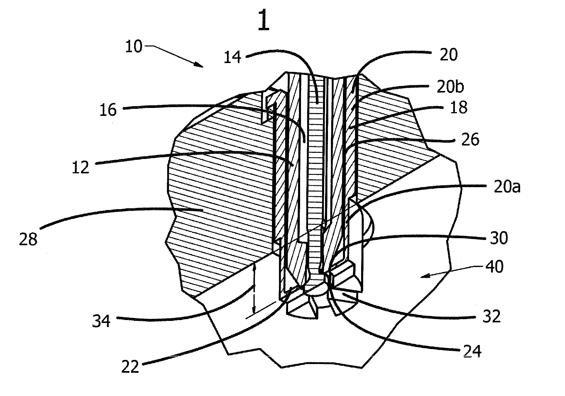
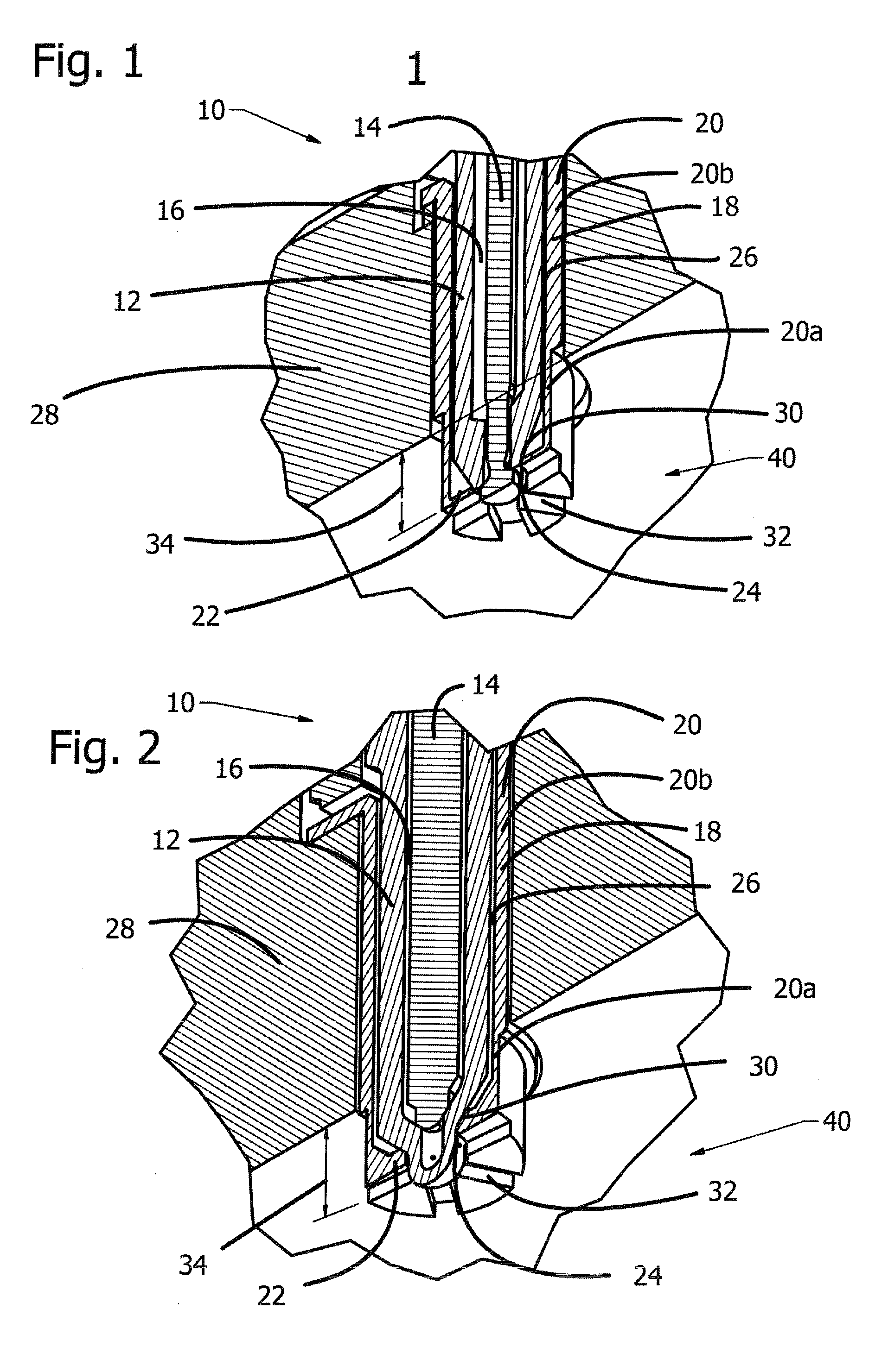
[0045]As shown in FIG. 1, a fuel injector 10 in accordance with the invention includes an injector body 12 defining an interior cavity in which a poppet or fuel metering valve body 14 reciprocates. A fuel passage 16 is defined between an inner surface of the injector body 12 and an outer surface of the valve body 14. These features are mostly conventional for a poppet style fuel injector 10 and shown to enable explanation of the invention. Thus, the invention is not limited to any particular form of injector body 12 and valve body 14 and is applicable to fuel injectors with other forms and shapes of these components, such as illustrated in FIG. 2. The manner in which the injector body 12 and valve body 14 cooperate to provide the known functions of a fuel injector are known to those skilled in the art, and described, for example, in U.S. Pat. No. 7,942,349.

[0046]In accordance with the invention, a deflector member 18 is arranged around the injector body 12, which deflector member 18...


PUM


Abstract

Method for preventing carbon build-up on fuel spray guiding surfaces proximate a nozzle of a fuel injector. Liquid fuel handling surfaces of the fuel injector can remain cool while providing very hot surfaces to burn off carbon particles before carbon deposits can build up and change the spray characteristics. In the method, a spray guiding structure guides the fuel spray after exiting from the fuel injector and a deflector member is arranged around the injector body. The spray guiding structure is thermally insulated from the fuel injector, and this thermal insulation enables the spray guiding structure to be heated to a temperature above about 900° F. to prevent build up of carbon thereon.

Description

FIELD OF THE INVENTION[0001]The present invention relates generally to an arrangement and method for preventing carbon formation in spray guiding structures and more specifically to an arrangement and method for preventing carbon formation in spray guiding structures of fuel injectors. The present invention also relates generally to arrangements and methods for enabling improved heating of the spray medium of fuel injectors to aid vaporization and atomization of the spray, and / or for preventing cracking of the fuel during the heating process.BACKGROUND OF THE INVENTION[0002]It is well known that surfaces in engines which operate above about 900° F. or below about 400° F. do not accumulate carbon. In the first case at temperatures above about 900° F., carbon accumulates, but is burned off. In the second case at temperatures below about 400° F., fuel and oil do not thermally decompose and carbon does not form.[0003]Fuel injectors have historically operated in the cold region of the sp...

Claims


Application Information

Patent Timeline
Patent Type & Authority Applications(United States)
IPC IPC(8): F02M53/04
CPCF02M53/046F02M61/18F02M2200/06
Inventor MEYER, ANDREW E.
Owner MEYER ANDREW E
Why Eureka
Try Eureka