Image display apparatus and method for controlling the same

Active Publication Date: 2014-07-17
CANON KK
View PDF14 Cites 15 Cited by
  • Summary
  • Abstract
  • Description
  • Claims
  • Application Information

AI Technical Summary

Benefits of technology

[0021]According to the present invention, it is possible to simultaneously attain both of the improvement in the quality of a displayed image to be achieved by suppressing the uneven luminance of the displayed image and the suppression of the delay ranging from

Problems solved by technology

A display apparatus, in which a screen image is displayed by adjusting the transmission amount of the light emitted from a backlight, as exemplified by a liquid crystal display apparatus, undergoes the occurrence of such a phenomenon called “misadjusted black level” that even a portion, at which the black is intended to be expressed, seems to be bright, and t

Method used


Image

  • Image display apparatus and method for controlling the same
  • Image display apparatus and method for controlling the same
  • Image display apparatus and method for controlling the same

Examples


first embodiment

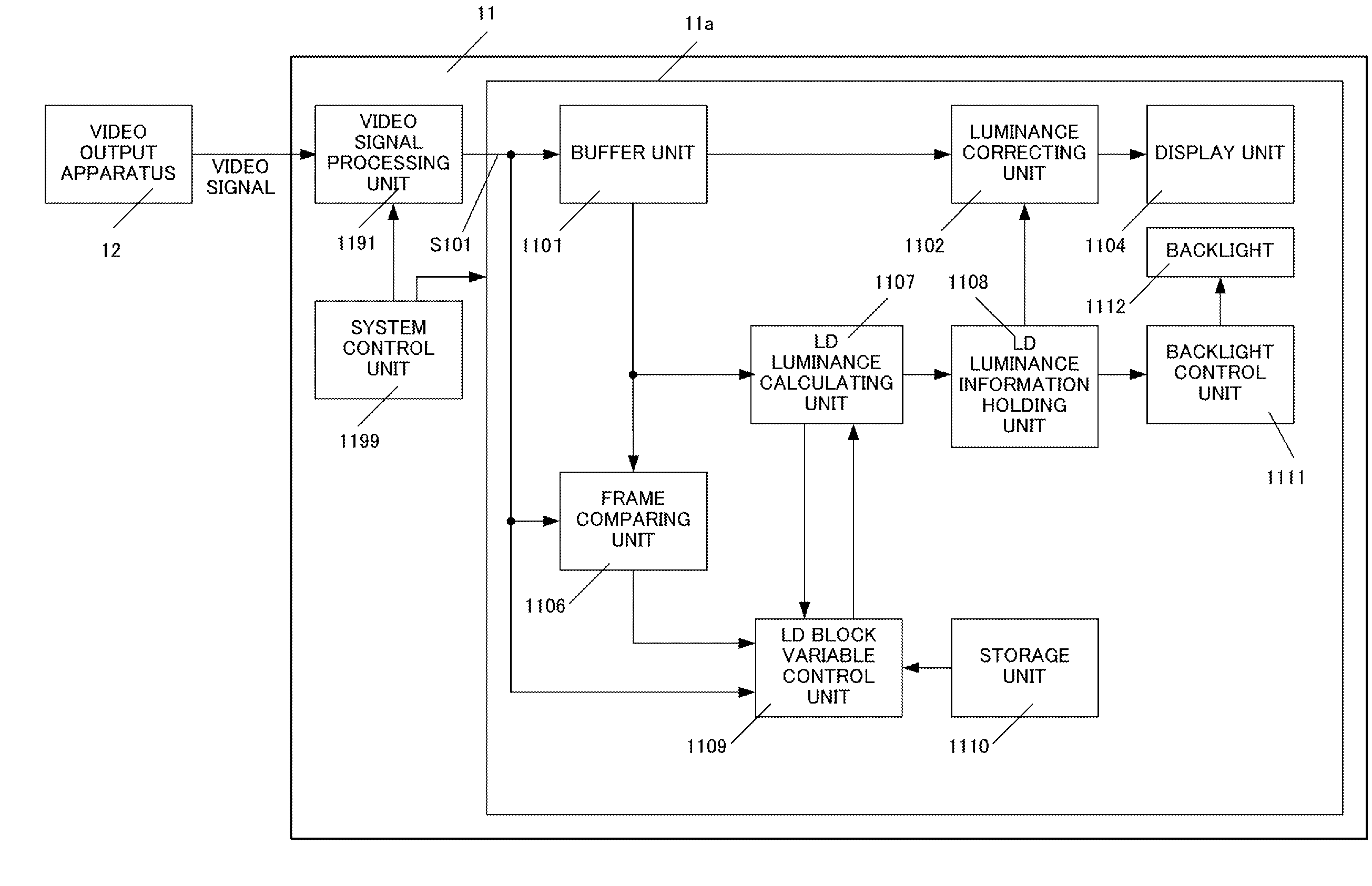
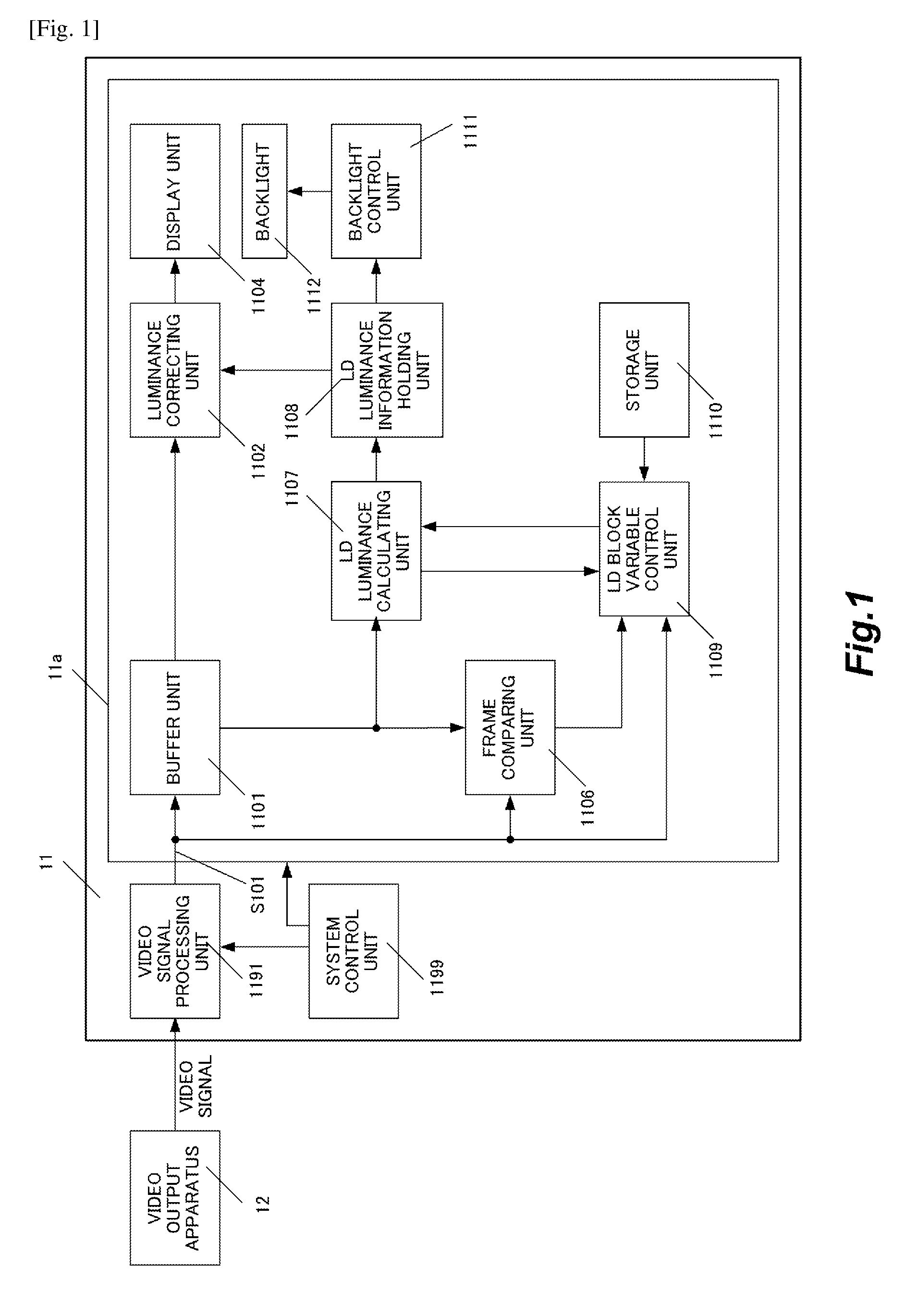
[0041]FIG. 1 shows a schematic arrangement of an image display apparatus according to a first embodiment of the present invention. With reference to FIG. 1, the image display apparatus 11 comprises a video signal processing unit 1191, a system control unit 1199, a local dimming (hereinafter referred to as “LD”) control device (controller) 11a, a display unit 1104, and a backlight 1112 (light emitting unit). The image display apparatus 11 displays a screen image (picture) on the basis of the video signal (image data) inputted from a video output apparatus 12. The video output apparatus 12 is, for example, PC (personal computer) or a DVD player.

[0042]The backlight 1112 is divided into a plurality of light source blocks for which the light emission can be controlled independently. In this embodiment, the light emission of the backlight 1112 is controlled in units of LD blocks (light emission control blocks) each composed of one or more light source blocks. In other words, as shown in a...

second embodiment

[0108]In the first embodiment, the example has been explained, in which the number of pixels of the video signal, the frame cycle, and the contents of the image data are investigated, and the number of block divisions in the LD control is determined depending on the obtained result. In a second embodiment, an example will be explained, in which the LD luminance information is included in the additional information of the inputted video signal. The following explanation will be made principally about the difference from the first embodiment.

[0109]FIG. 8 shows functional blocks of an image display apparatus according to the second embodiment. The difference from the image display apparatus according to the first embodiment shown in FIG. 1 resides in that the LD luminance information holding unit 1108 of the first embodiment is replaced with an LD luminance information holding / switching unit 1152 in the second embodiment and that an LD information detecting unit 1151 is added in the se...

third embodiment

[0119]In the second embodiment, the example has been explained, in which the LD luminance information is added to the video signal. Ina third embodiment, an example will be explained, in which the LD luminance information is inputted via an interface which is distinct from the input line for the video signal. The following explanation will be made principally about the difference from the first and second embodiments.

[0120]FIG. 11 shows functional blocks of an image display apparatus according to the third embodiment. The difference between the image display apparatus of this embodiment and the image display apparatus according to the second embodiment shown in FIG. 8 resides in that an external I / F control unit 1153 is added and that the LD information detecting unit 1151 has the function to detect the LD luminance information inputted from the external I / F control unit 1153.

[0121]The LD information detecting unit 1151 monitors whether or not the LD luminance information and the fr...


PUM


Abstract

The present invention resides in an image display apparatus for displaying an image on the basis of image data; the image display apparatus comprising light emitting unit having a plurality of light sources for performing light emission that can be independently controlled respectively; setting unit which sets light emission control blocks for controlling one light source or the plurality of light sources with a common brightness; brightness determining unit which determines the light emission brightness of each of the light emission control blocks on the basis of the image data; and control unit which controls the light emission of the light emitting unit for each of the light emission control blocks in accordance with the light emission brightness determined by the determining unit; wherein the setting unit sets a size of the light emission control block of the light emitting unit depending on an amount of motion of the image.

Description

TECHNICAL FIELD[0001]The present invention relates to an image display apparatus and a method for controlling the same.BACKGROUND ART[0002]A display apparatus, in which a screen image is displayed by adjusting the transmission amount of the light emitted from a backlight, as exemplified by a liquid crystal display apparatus, undergoes the occurrence of such a phenomenon called “misadjusted black level” that even a portion, at which the black is intended to be expressed, seems to be bright, and this phenomenon brings about a factor to deteriorate or decrease the image quality (deteriorate or decrease the contrast) in some cases. This phenomenon occurs such that a liquid crystal unit, which adjusts the transmission amount of the light emitted from the backlight, cannot shut off the light sufficiently, and a part of the light is consequently transmitted.[0003]In view of the above, the following technique is used. That is, the backlight is divided into a plurality of light source blocks...

Claims


Application Information

Patent Timeline
IPC IPC(8): G09G3/36
CPCG09G3/36G09G3/3426G09G2320/0646G09G2320/103G09G2360/16
Inventor SHIBAMIYA, YOSHIKAZUMASUDA, CHIKAMORITA, ATSUSHIKAMAHARA, JOJI
Owner CANON KK
Why Eureka
Try Eureka