Organic light emitting display device

a technology of light-emitting display device and organic light-emitting material, which is applied in the direction of display means, instruments, signs, etc., can solve the problems of non-uniform image display and image-generating phenomenon of vertical line defects

Inactive Publication Date: 2014-07-17
SAMSUNG DISPLAY CO LTD
View PDF11 Cites 43 Cited by
  • Summary
  • Abstract
  • Description
  • Claims
  • Application Information

AI Technical Summary

Benefits of technology

[0026]The second demultiplexer may be configured to supply the second data signals to the plurality of data lines coupled to the second and third pixels in a constant order corresponding to the second control signals.
[0027]The first demultiplexer may be configured to supply the first data signals to the data lines coupled to the first pixels in a supplying order that changes in each frame according to the first control signals.
[0028]The demultiplexer controller may be configured to supply the first control signals in a first order during an i (i indicates an integer) frame period, and may be configured to supply the first control signals in a second order, which is reversed with respect to the first order, during an i+1 frame period.
[0029]The demultiplexer controller may be configured to change a supplying order of the first control signals for each horizontal period.
[0030]The demultiplexer controller may be configured to supply the first control signals in a first order and then a second order, which is a reverse order with respect to the first order, based on the horizontal period.

Problems solved by technology

However, when the last control signal and the scan signal are overlapped with each other, the amount of voltage charged between pixels corresponding to the same data signal may be different, and therefore, a non-uniform image may be displayed.
Furthermore, when the last control signal is overlapped with the scan signal a phenomenon of vertical line-shaped defects may be generated in the image.

Method used


Image

  • Organic light emitting display device
  • Organic light emitting display device
  • Organic light emitting display device

Examples


first embodiment

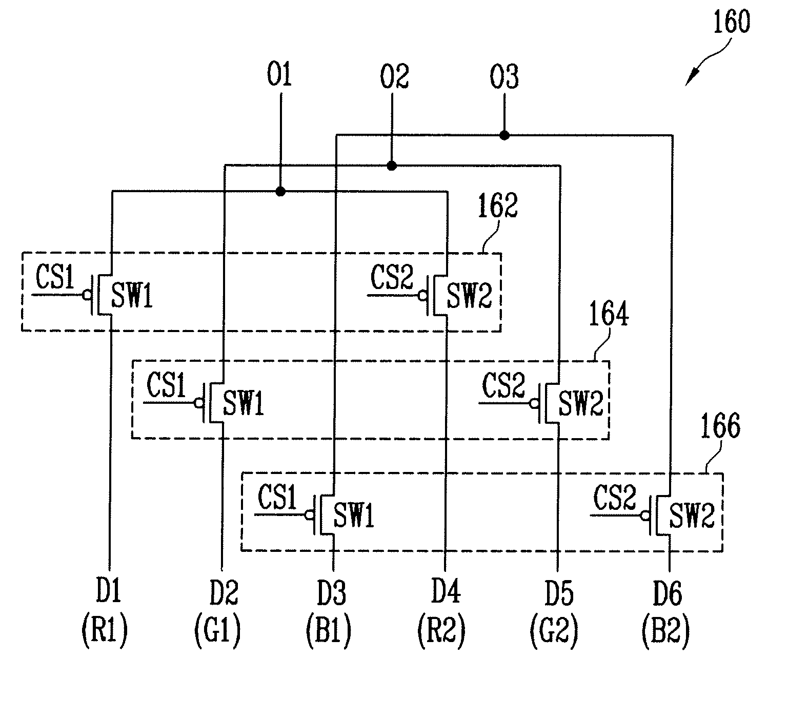
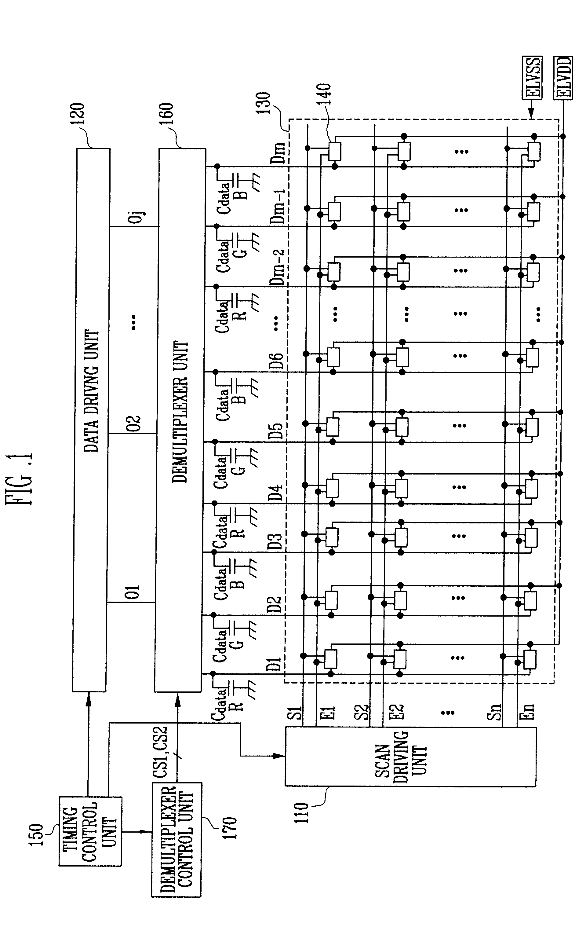
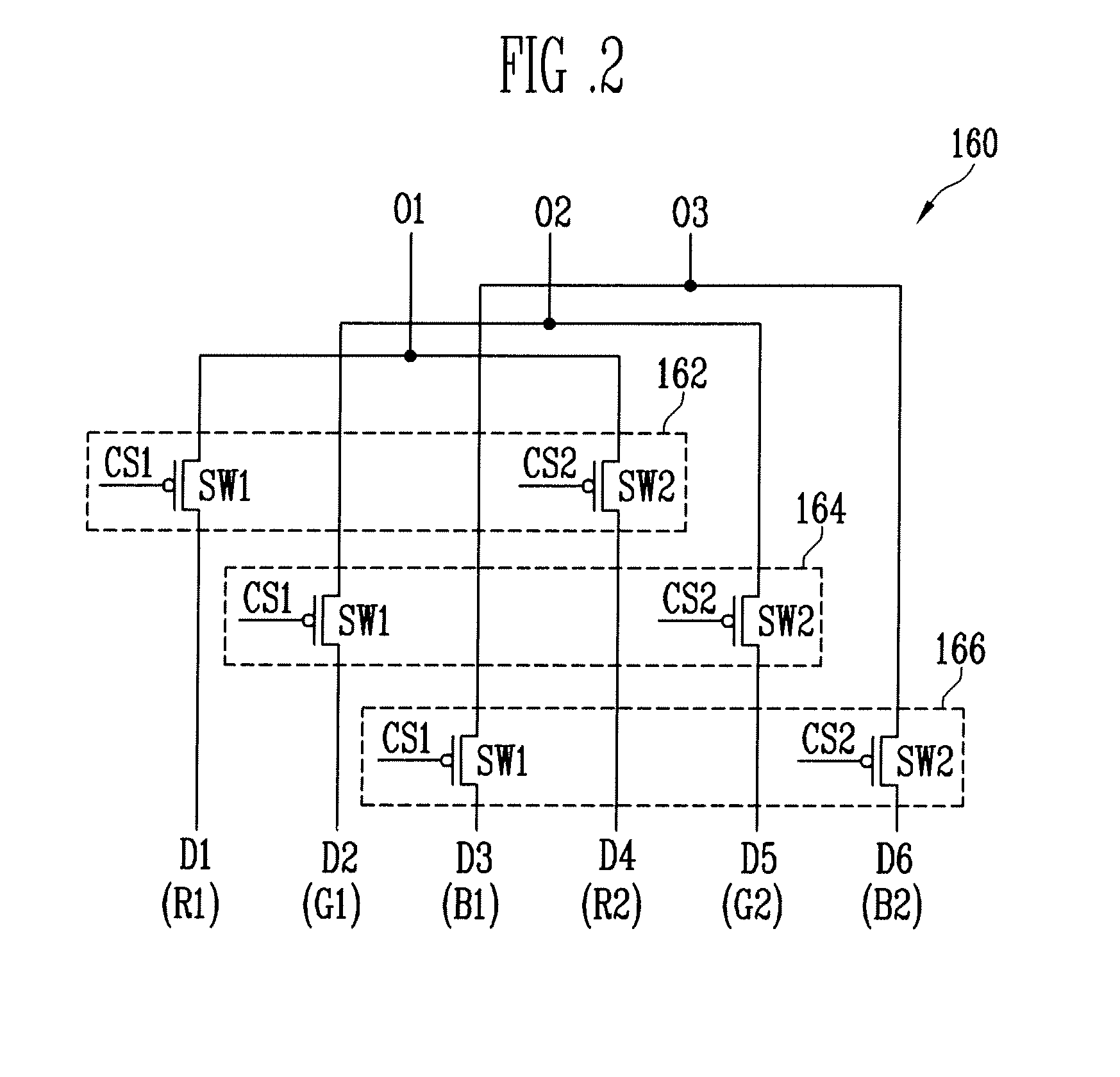
[0055]FIG. 2 is a schematic circuit diagram of a demultiplexer unit 160 according to the present invention. In FIG. 2, the demultiplexers 162, 164, and 166 coupled to a first output line O1, a second output line O2, and a third output line O3, respectively, will be described for convenience of explanation.

[0056]Referring to FIG. 2, the demultiplexer unit 160 according to the first embodiment of the present invention includes the demultiplexers 162, 164, and 166 respectively coupled to the output lines O1 to O3. Here, each of the demultiplexers 162, 164, and 166 transmits a plurality of the data signals, supplied to the output lines O1 to O3, to the pixels 140 configured to emit the same color.

[0057]In other words, a first demultiplexer 162 transmits the plurality of data signals supplied to the first output line O1 to the first pixels, which are configured to generate a red color light. To this end, the first demultiplexer 162 is coupled to the first data line D1 and the fourth data...

second embodiment

[0070]FIGS. 4A and 4B are timing diagrams illustrating the method of driving the demultiplexer shown in FIG. 2. When FIGS. 4A and 4B are described, detailed descriptions of the same parts with respect to FIGS. 3A and 3B may be omitted.

[0071]Referring to FIGS. 4A and 4B, the supplying order of the first and second control signals CS1 and CS2 is changed for a frame (e.g., frame by frame) and horizontal period unit according to the second embodiment of the present invention.

[0072]For example, during the i horizontal period iH of the i frame iF, the scan signals are supplied in an order of the first control signal CS1 followed by the second control signal CS2, and the scan signals are supplied in an order of the second control signal CS2 followed by the first control signal CS1 during the i+1 horizontal period 1H.

[0073]In addition, during the i horizontal period iH of the i+1 frame i+iF, the control signals are supplied in the order of the second to first control signals CS2 and CS1, an...

third embodiment

[0085]FIG. 7 is a schematic circuit diagram showing a demultiplexer unit 160 of the present invention. FIG. 7 will be described with reference to differences with respect to the previously-described embodiments of the present invention.

[0086]Referring to FIG. 7, the demultiplexer unit 160 according to the third embodiment of the present invention includes the demultiplexer 163′ coupled to the output line O2 and the demultiplexer 165′ coupled to the output lines O1 and O3. Here, the fourth demultiplexer 163′ transmits the data signal to the pixels 140 that are configured to emit a same color of light. In addition, the fifth demultiplexer 165′ transmits the data signal to the adjacent pixels 140 for emitting different colors of light.

[0087]For example, the fourth demultiplexer 163′ may transmit a corresponding data signal to the first pixels configured to emit a red color light. To this end, the fourth demultiplexer 163′ includes the first switching device SW1 and the second switchin...


PUM


Abstract

Provided is an organic light emitting display device including: a scan driver configured to supply a scan signal to a scan line during a scan period of a horizontal period; a data driver configured to supply a plurality of data signals to a plurality of output lines during a data period of the horizontal period; a demultiplexer configured to transmit the data signals through the output lines to a plurality of data lines according to a plurality of control signals; and a demultiplexer controller configured to supply the control signals to the demultiplexer, with a supply order of the control signals being changed for each frame.

Description

CROSS-REFERENCE TO RELATED APPLICATION[0001]This application claims priority to and the benefit of Korean Patent Application No. 10-2013-0005455, filed on Jan. 17, 2013, in the Korean Intellectual Property Office, the entire content of which is incorporated herein by reference.BACKGROUND[0002]1. Field[0003]Embodiments of the present invention relate to an organic light emitting display device.[0004]2. Description of the Related Art[0005]Recently, various flat panel display devices having reduced weight and volume as compared to the weight and volume of cathode ray tubes, have been developed. Flat panel display devices include, for example, liquid crystal displays, field emission displays, plasma display panels, organic light emitting display devices, and the like.[0006]An organic light emitting display device among flat panel display devices, displays an image using organic light emitting diodes capable of generating light by recombination between electrons and holes. The organic li...

Claims


Application Information

Patent Timeline
Patent Type & Authority Applications(United States)
IPC IPC(8): G09G3/32
CPCG09G3/3208G09G3/3275G09G2310/0297G09G2320/0233G09G2320/0242G09F7/06G09F15/0012G09F15/0068G09F2007/1847
Inventor EOM, KI-MYEONGKIM, MI-HAE
Owner SAMSUNG DISPLAY CO LTD
Why Eureka
Try Eureka