Three-dimensional imaging system based on stereo hologram

a three-dimensional imaging and stereo hologram technology, applied in the field of three-dimensional imaging systems, can solve the problems of inconvenient wearing of 3d glasses, image distortion, and the resolution of an image projected to a viewer's eyes at a position within a viewing zone is too low, and achieve the effect of smooth providing continuous parallax

Active Publication Date: 2014-07-17
KONYANG UNIV IND ACADEMIC COOPERATION FOUND
View PDF6 Cites 13 Cited by
  • Summary
  • Abstract
  • Description
  • Claims
  • Application Information

AI Technical Summary

Benefits of technology

[0030]According to the present invention, high-quality three-dimensional stereoscopic images can be realized by smoothly providing continuous parallax at a viewer's position by increasing the number of pixels included in each pixel cell.

Problems solved by technology

A system for obtaining 3D effect using 3D glasses has inconvenience of wearing 3D glasses and a problem of image distortion.
However, because resolution of an image projected to a viewer's eyes at a position within a viewing zone is too low due to limitation in resolution of a display panel, 3D products using a multi-view imaging system have not been well received by consumers and are still not fully commercialized.
The major problem is that it cannot generate a natural 3D image that causes no eye fatigue for viewers.
However, the actual possibility of realizing the Zebra hologram is extremely low because of cost and structural problems: Arranging the two-dimensional image points with the resolution of a display panel and with a gap between adjacent image points unperceived by a viewer, with use of a display device and other required components for making image point will cause the problems.
However, such a method has a problem in creating images capable of generating continuous parallax at a viewer's position because it is very difficult to make hundreds of pixels be in each pixel cell.
However, because the photoplate doesn't allow recording in real time, it is difficult to display a video image.
Additionally, because a hologram recording device for continuous recording and deleting should be included, this method can be hardly used for display.

Method used


Image

  • Three-dimensional imaging system based on stereo hologram
  • Three-dimensional imaging system based on stereo hologram
  • Three-dimensional imaging system based on stereo hologram

Examples


Embodiment Construction

[0038]Hereinafter, constitution of a three-dimensional imaging system based on a stereo hologram according to an embodiment of the present invention will be described in detail with reference to the annexed drawings.

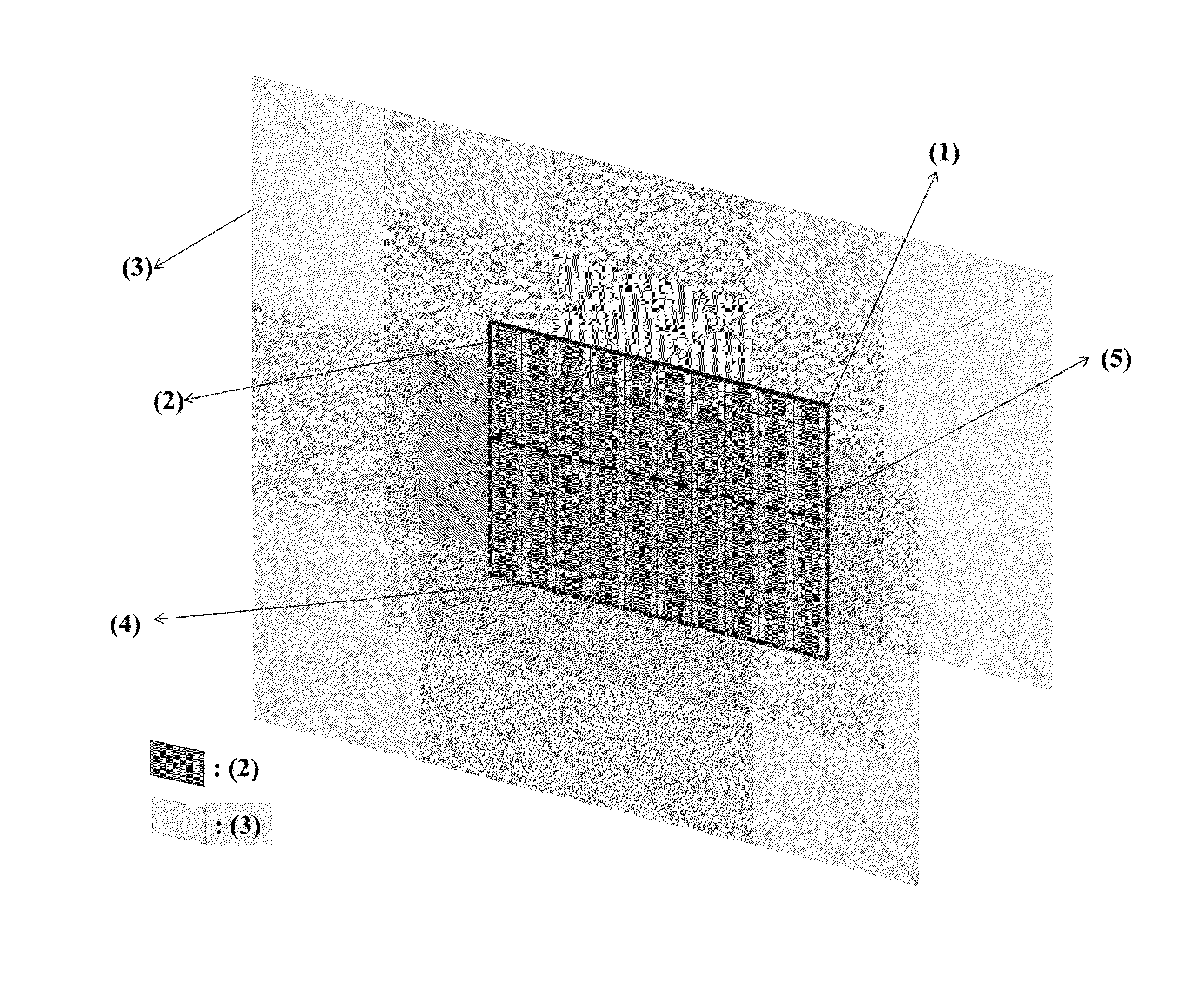
[0039]FIG. 1 is a conceptual view illustrating a general image reproduction principle of a two-dimensional stereo hologram. A two-dimensional stereo hologram 1 depicted in FIG. 1 includes 10×10 point-image holograms 2. When an image is reproduced, a view image is reproduced at each of the point-image holograms 2 and is projected as a magnified image 3. The magnified images from all of the point-image holograms 2 are overlapped at an overlapping space 4. Because a composite image including one pixel from each of the magnified images 3 is projected to any point in the overlapping space 4, the overlapping space 4 becomes a viewing zone. At this time, the image projected to each point of the overlapping zone 4 from the two-dimensional stereo hologram 1 is composed of 10×10 p...


PUM


Abstract

A three-dimensional imaging system based on a stereo hologram is disclosed. Images composed of sub-images having the same vertical-horizontal resolutions which are generated at plural image projection modules having a two-dimensional arrangement structure are projected to a prism array plate or a transmission-type diffusion plate, and are converted into light points, i.e., image points through a microlens array unit. A diffusion plate used as an image display screen is mounted to a position at which images diffused from the light points intersect with images diffused from the adjacent light points.

Description

STATEMENT REGARDING SPONSORED RESEARCH[0001]This inventions was partly supported by the Korean Ministry of Culture, Sports and Tourism and the Korea Creative Contents Agency (Kocca) under the Culture Technology (CT) Research and Development Program 2013, and IT R&D program of MSIP / MOTIE / KEIT[10039169, Development of Core Technologies for Digital Holographic 3-D Display and Printing System]”, and the IT R&D program of MKE / KEIT[K1001810035337, development of interactive wide viewing zone SMV optics of 3D display], and GigaKOREA project, [GK13D0100, Development of Telecommunications Terminal with Digital Holographic Table-top Display].BACKGROUND OF THE INVENTION[0002]1. Field of the Invention[0003]The present invention relates to a three-dimensional imaging system, and more particularly, to a three-dimensional imaging system based on a stereo hologram, in which images composed of sub-images having the same vertical-horizontal resolutions which are generated at plural image projection m...

Claims


Application Information

Patent Timeline
Patent Type & Authority Applications(United States)
IPC IPC(8): G03H1/26G02B30/10H04N13/363H04N13/388
CPCG03H1/268H04N13/363H04N13/302H04N13/32H04N13/388G02B30/10G03H1/04H04N13/00G03H2223/19G03H2223/18G02B30/27G02B30/34
Inventor SON, JUNG YOUNG
Owner KONYANG UNIV IND ACADEMIC COOPERATION FOUND
Why Eureka
Try Eureka