Lighting Unit and Light Bar having the Same

a technology of light bar and light unit, which is applied in the direction of lighting and heating apparatus, semiconductor devices for light sources, and support devices for lighting, etc. it can solve the problems of reduced light bar brightness, limited arrangement of leds on printed circuit boards, and consuming a long time in the manufacturing process of led light bars, so as to reduce the manufacturing process time of light bars, reduce the distance between two adjacent lighting units, and improve the effect of lighting unit replacemen

Inactive Publication Date: 2014-07-17
LEXTAR ELECTRONICS CORP
View PDF7 Cites 18 Cited by
  • Summary
  • Abstract
  • Description
  • Claims
  • Application Information

AI Technical Summary

Benefits of technology

[0021]In the aforementioned embodiments of the present invention, since the first male connection terminal of the first end portion of the lighting unit can be coupled to the first female connection terminal of the second end portion of another lighting unit adjacent to the lighting unit, the plural lighting units can be connected in series to form the light bar. The light bar of the present invention does not need to have a printed circuit board used to a conventional LED light bar, and the SMT process does not need to apply to the light bar to solder LEDs to a printed circuit board. As a result, the manufacturing process time of the light bar is reduced, and users can assemble the light bar from the lighting units by themselves or easily replace the lighting units of the light bar.
[0022]In addition, the light emitting surfaces of the lighting units of the light bar can face the same direction or different directions, so that the light emitting angle of the light bar is increased. The light bar may include the interval units located between the lighting units, such that a distance between two adjacent lighting units can be increased, and the light emitted by the light bar has significant variability.

Problems solved by technology

As such, the arrangement of the LEDs on the printed circuit board is limited by the layout of electric circuits of the printed circuit board.
In automatic production of the LED light bar, the LEDs are soldered on the printed circuit board by means of surface mount technology (SMT), and so this usually consumes a long time in the manufacturing process of the LED light bar.
In addition, after long term use of the conventional LED light bar, some LEDs may be totally damaged or reduced in brightness.
Since the LEDs are soldered on the printed circuit board, it is difficult to replace the damaged LEDs.

Method used


Image

  • Lighting Unit and Light Bar having the Same
  • Lighting Unit and Light Bar having the Same
  • Lighting Unit and Light Bar having the Same

Examples


Embodiment Construction

[0036]Reference will now be made in detail to the present embodiments of the invention, examples of which are illustrated in the accompanying drawings. Wherever possible, the same reference numbers are used in the drawings and the description to refer to the same or like parts.

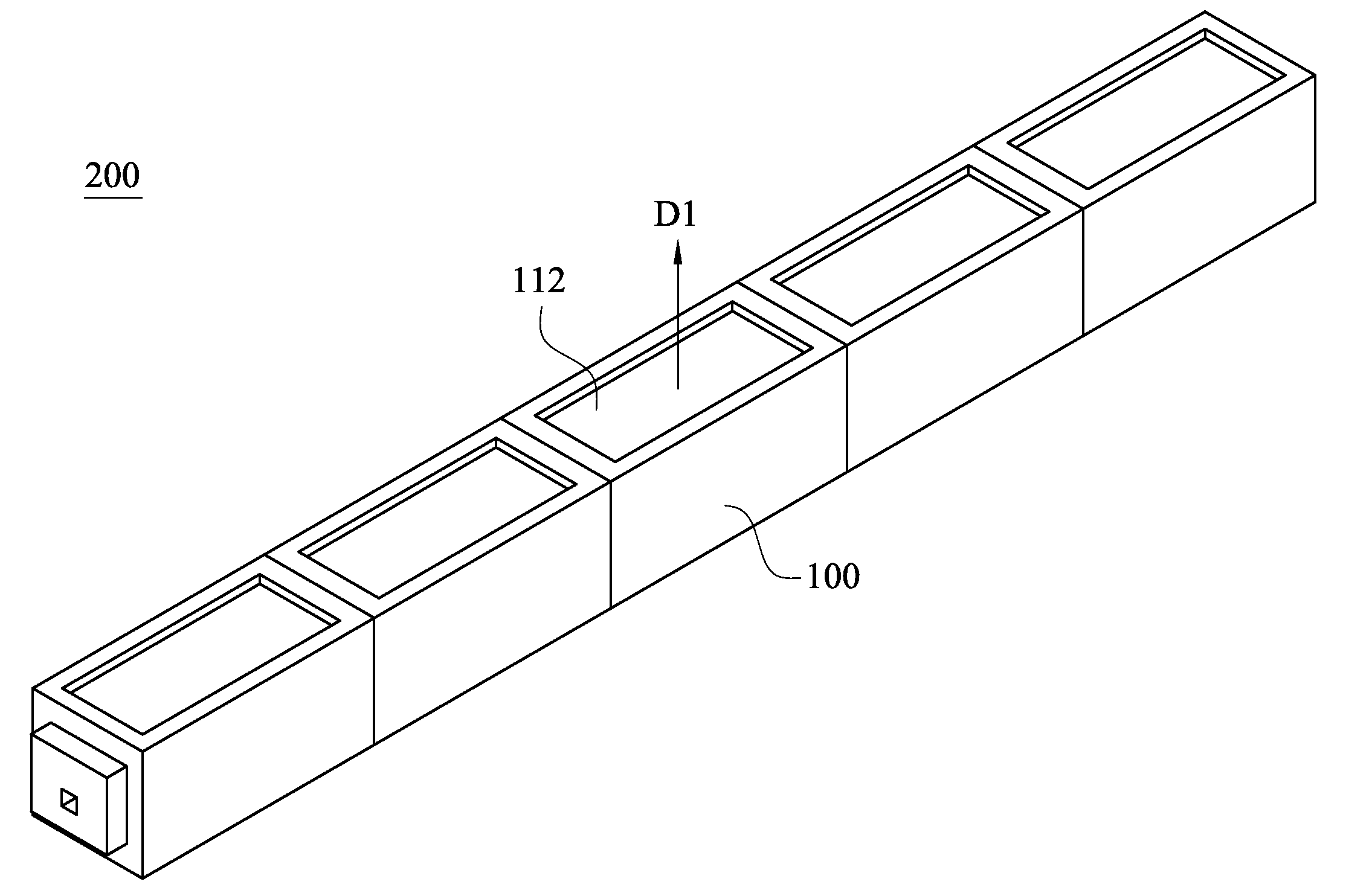
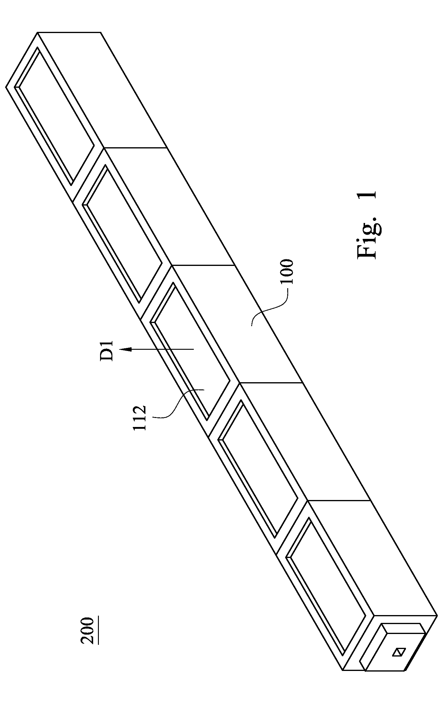
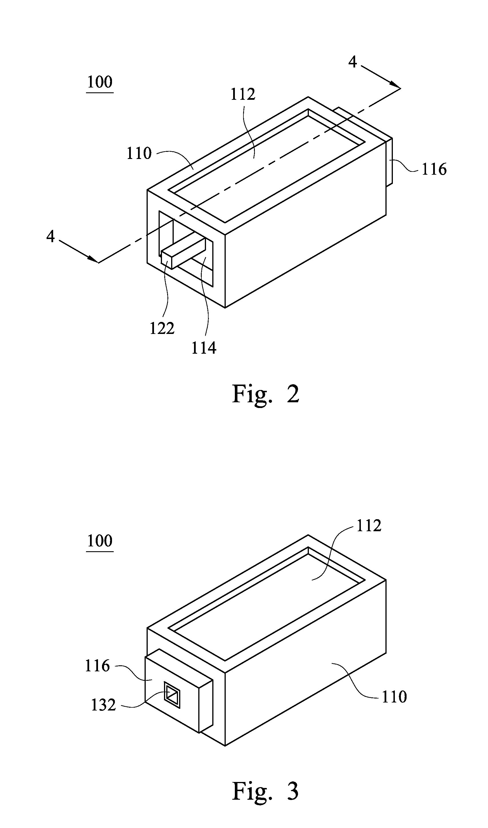
[0037]FIG. 1 is a perspective view of a light bar 200 according to one embodiment of the present invention. FIG. 2 is a perspective view of one of lighting units 100 of the light bar 200 shown in FIG. 1. As shown in FIG. 1 and FIG. 2, the light bar 200 includes N lighting units 100 that are connected in series, and N is a natural number. In this embodiment, N is equal to 5, but the present invention is not limited in this regard.

[0038]Each of the lighting units 100 includes a cup body 110 that has a light emitting surface 112. In this embodiment, the light emitting surfaces 112 of the lighting units 100 face the same direction D1, but in another embodiment, the light emitting surfaces 112 of the lighting units...


PUM


Abstract

A lighting unit is provided and includes a cup body, a substrate, a first conductive wire connector and a second conductive wire connector. The cup body has a light emitting surface, a first end portion, and a second end portion. The substrate is located in the concave accommodating cavity of the cup body. A lighting element is located on the substrate, and has a light emitting direction toward the light emitting surface. The first and second conductive wire connectors are respectively located at two sides of the substrate in the accommodating cavity. A portion of the first conductive wire connector protrudes from the surface of the first end portion to form a first male connection terminal. The second conductive wire connector is recessed in the surface of the second end portion to form a first female connection terminal.

Description

RELATED APPLICATIONS[0001]This application claims priority to Taiwan Application Serial Number 102101777, filed Jan. 17, 2013, which is herein incorporated by reference.BACKGROUND[0002]1. Field of Invention[0003]The present invention relates to a lighting unit and a light bar having the lighting unit.[0004]2. Description of Related Art[0005]Light emitting diodes (LEDs) are semiconductor elements. Along with the progress of technology, the LEDs are not only applied as indicators of electronic devices or lighting elements of display panels, but used in thin profile televisions, computer monitors, and general lighting apparatus. The LEDs have the advantages such as long lifespan, low energy consumption, small size, good shock resistance, and a wide variety of usages.[0006]A conventional LED light bar is equipped with the LEDs and a printed circuit board. The light bar is manufactured by soldering the LEDs on the printed circuit board. As such, the arrangement of the LEDs on the printed...

Claims


Application Information

Patent Timeline
Patent Type & Authority Applications(United States)
IPC IPC(8): F21K99/00
CPCF21K9/56F21K9/00F21S2/005F21Y2101/00F21Y2115/10H01L2224/48091H01L2224/48247H01L2924/00014
Inventor CHIN, SHIH-CHIEH
Owner LEXTAR ELECTRONICS CORP
Why Eureka
Try Eureka