Steam turbine comprising a thrust balance piston

Inactive Publication Date: 2014-07-17
SIEMENS AG
View PDF0 Cites 3 Cited by
  • Summary
  • Abstract
  • Description
  • Claims
  • Application Information

AI Technical Summary

Benefits of technology

[0016]The invention proceeds from the concept that inherent cooling of components is possible, in which a targeted pressure flow is made possible or is forced via different pressure levels. The pressure in the first pressure space is thus greater than the pressure in the third pressure space. The cooling channels which are arranged in such a way that they flow a

Problems solved by technology

The prior art concerning gas turbines therefore cannot be used for this reason to assess the subject matter of the present application.
However, a temperature increase, in particular, is not possible to an unlimited extent for material reasons.
The temperature resistance of the components is usually limited depending on the choice of material.
Without efficient cooling, substantially more expensive materials (for example, nickel-based alloys) would be necessary in the case of rising temperatures.
In the case of loading of customary steam turbines with higher steam

Method used


Image

  • Steam turbine comprising a thrust balance piston
  • Steam turbine comprising a thrust balance piston
  • Steam turbine comprising a thrust balance piston

Examples


Embodiment Construction

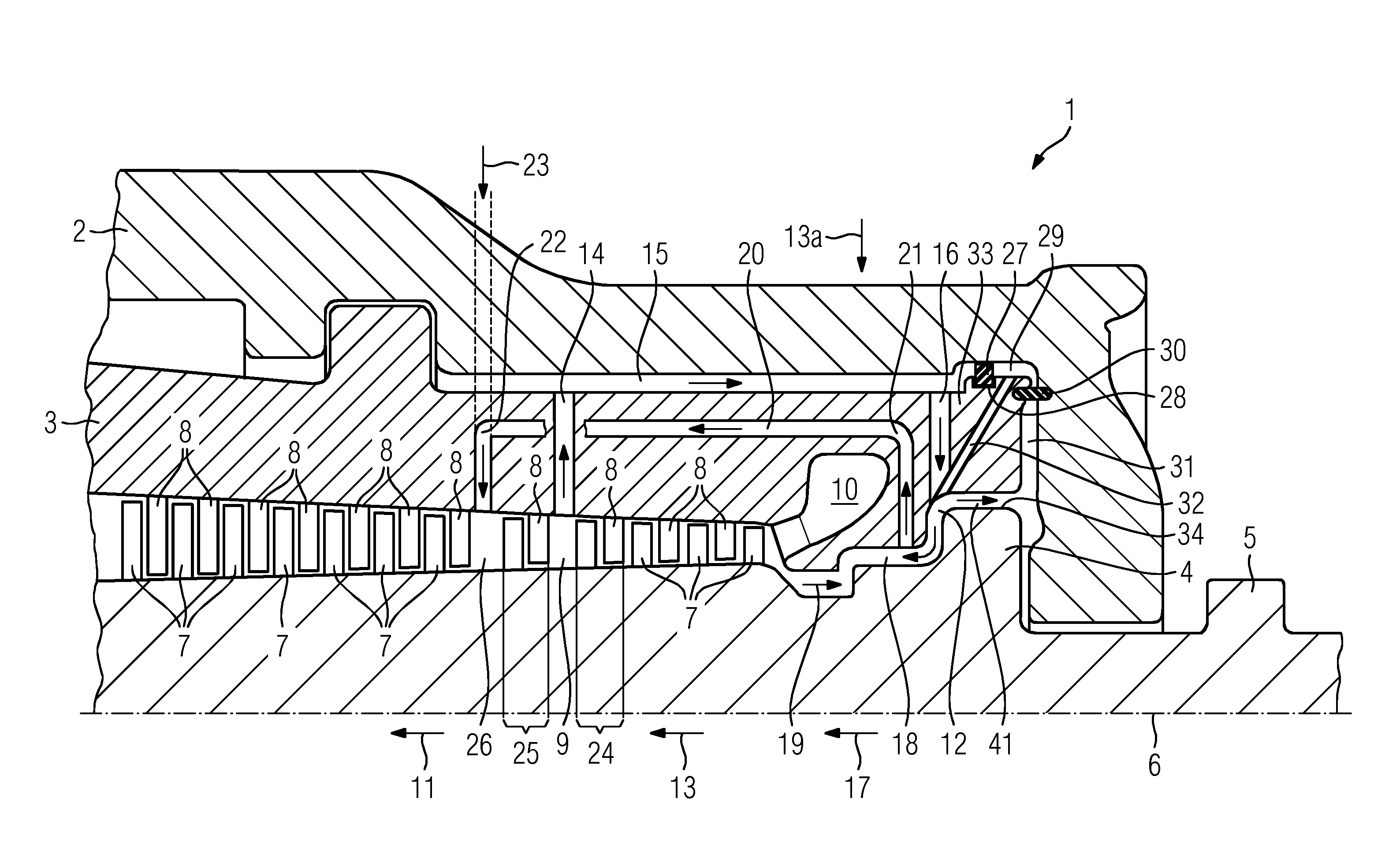
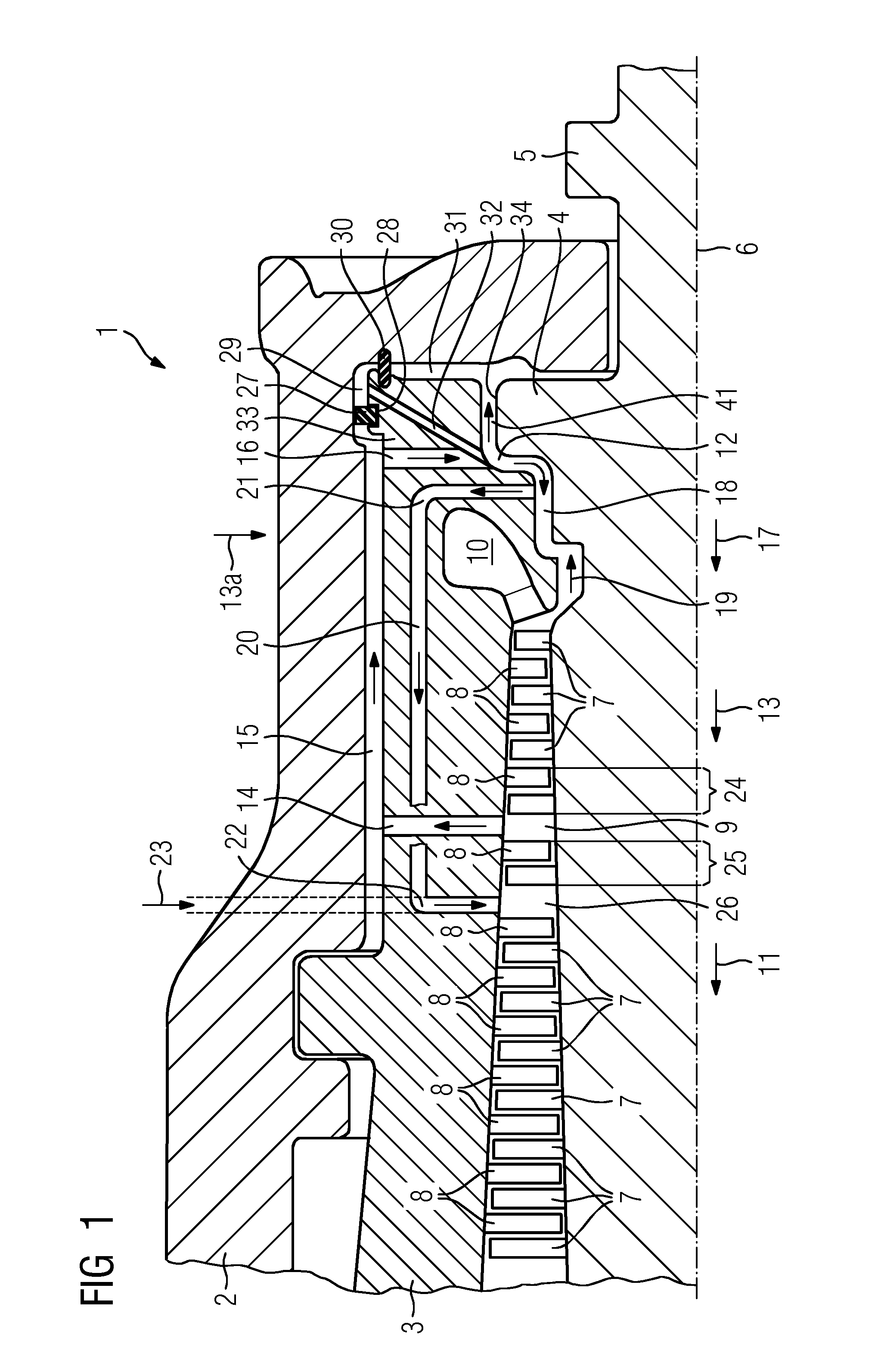
[0021]FIG. 1 shows a cross section through a steam turbine 1. The steam turbine 1 has an outer housing 2 and an inner housing 3. The inner housing 3 and the outer housing 2 have a fresh steam feed channel which is described in greater detail in FIG. 2. A rotor 5 which has a thrust compensating piston 4 is arranged in a rotationally mounted manner within the inner housing 3. The rotor is usually configured so as to be rotationally symmetrical about a rotational axis 6. The rotor 5 comprises a plurality of rotor blades 7. The inner housing 3 has a plurality of guide blades 8. A flow channel 9 is formed between the inner housing 3 and the rotor 5. The flow channel 9 comprises a plurality of blade stages which are formed in each case from a row of rotor blades 7 and a row of guide blades 8.

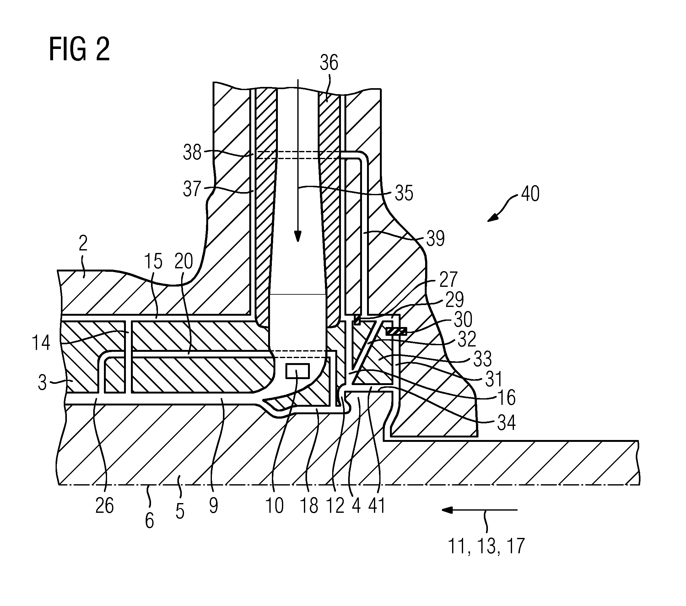
[0022]Fresh steam flows via the fresh steam feed channel into an inflow opening 10 and flows from there in a flow direction 11 through the flow channel 9 which extends substantially parallel to the ro...


PUM


Abstract

A cooling mechanism for a steam turbine is provided, which has, in the area of the valve connection a cooling channel, into which cooling steam flows from the flow channel, the steam then being fed as cooling steam in the area of the thrust balance piston.

Description

CROSS REFERENCE TO RELATED APPLICATIONS[0001]This application is the US National Stage of International Application No. PCT / EP2012 / 065065 filed Aug. 1, 2012, and claims the benefit thereof. The International Application claims the benefit of European Application No. EP 11176574.9 filed Aug. 4, 2011. All of the applications are incorporated by reference herein in their entirety.FIELD OF INVENTION[0002]The invention relates to a steam turbine having an outer housing and an inner housing, a rotor, comprising a plurality of rotor blades, which has a thrust compensating piston being arranged in a rotationally mounted manner within the inner housing, the inner housing having an inner housing end region which is formed around the thrust compensating piston, a seal which seals a third pressure space which is arranged between the inner housing region and the outer housing, the inner housing having a feed channel which connects the first pressure space to a thrust compensating piston pre-spac...

Claims


Application Information

Patent Timeline
IPC IPC(8): F01K3/04
CPCF01K3/04F01D3/04F05D2220/31F05D2260/20
Inventor HOLDER, MARTINALENZ, CHRISTIANPIEPER, NORBERTPOTTER, RUDOLFSCHLEHUBER, DOMINICZANDER, UWE
Owner SIEMENS AG
Why Eureka
Try Eureka