Blood treatment systems and methods

Inactive Publication Date: 2014-07-17
DEKA PROD LLP
View PDF9 Cites 110 Cited by
  • Summary
  • Abstract
  • Description
  • Claims
  • Application Information

AI Technical Summary

Benefits of technology

[0069]A further aspect of the invention is directed to a method for returning extracorporeal blood to a patient, in an extracorporeal treatment system, using a source of compressed gas in the event of a power failure. The extracorporeal treatment system comprises a filter having a semi-permeable membrane that separates a blood flow path to from an electrolyte solution flow path. The compressed gas is in valved communication with an electrolyte solution container, and the electrolyte solution container is in valved communication with the electrolyte solution flow path. The method comprises, in response to a termination of electrical power to one or more electrically actuated valves that control a distribution of compressed gas or a dis

Problems solved by technology

Many factors make hemodialysis inefficient, difficult, and expensive.
These factors include the complexity of hemodialysis, the safety concerns related to hemodialysis, and the very

Method used


Image

  • Blood treatment systems and methods
  • Blood treatment systems and methods
  • Blood treatment systems and methods

Examples


Embodiment Construction

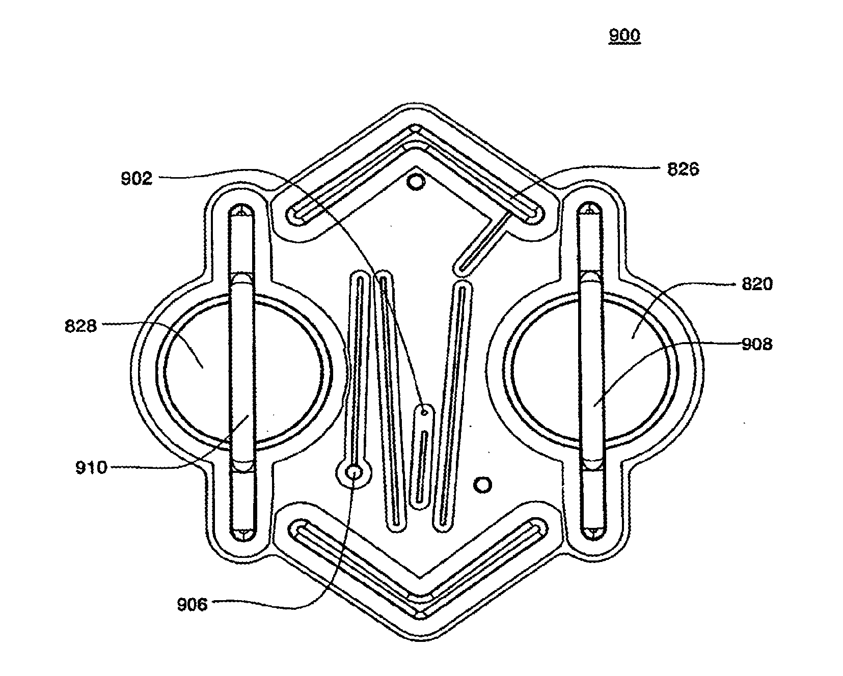
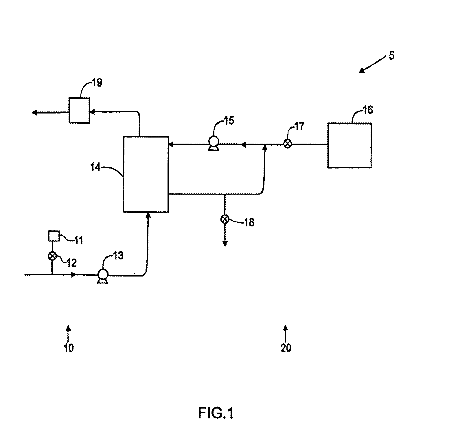
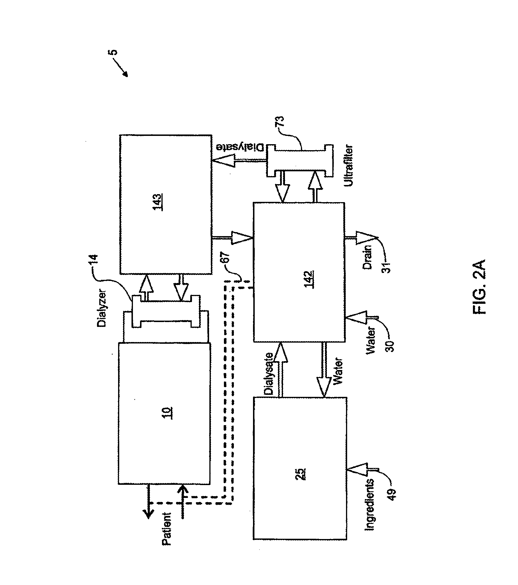
[0297]The present invention generally relates to hemodialysis and similar extracorporeal blood treatment systems, including a variety of systems and methods that would make hemodialysis more efficient, easier, and / or more affordable. One aspect of the invention is generally directed to new fluid circuits for fluid flow. In one set of embodiments, a hemodialysis system may include a blood flow path and a dialysate flow path, where the dialysate flow path includes one or more of a balancing circuit, a mixing circuit, and / or a directing circuit. Preparation of dialysate by the mixing circuit, in some instances, may be decoupled from patient dialysis. In some cases, the circuits are defined, at least partially, within one or more cassettes, optionally interconnected with conduits, pumps, or the like. In one embodiment, the fluid circuits and / or the various fluid flow paths may be at least partially isolated, spatially and / or thermally, from electrical components of the hemodialysis syst...


PUM


Abstract

The present invention generally relates to hemodialysis and similar dialysis systems, including a variety of systems and methods that would make hemodialysis more efficient, easier, and/or more affordable. One aspect of the invention is generally directed to new fluid circuits for fluid flow. According to one aspect, a blood pump is configured to pump blood to a dialyzer of a hemodialysis apparatus, the blood pump comprising a pneumatically actuated or controlled reciprocating diaphragm pump. In an embodiment, the diaphragm of the pump comprises a flexible membrane formed or molded to generally conform to a curved inner wall of a pumping chamber or control chamber of the pump, wherein the diaphragm is pre-formed or molded to have a control side taking a convex shape, so that any elastic tension on the diaphragm is minimized when fully extended into a control chamber of the pump.

Description

RELATED APPLICATIONS[0001]This application is a continuation in part of U.S. patent application Ser. No. 13 / 624,460, filed on Sep. 21, 2012, and published as U.S. Patent Application Publication No. US 2013 / 0074959; which is a continuation of U.S. patent application Ser. No. 11 / 871,680, filed on Oct. 12, 2007, and issued as U.S. Pat. No. 8,273,049; which claims the benefit, under 35 U.S.C. §119(e), of U.S. Provisional Patent Application No. 60 / 904,024, filed on Feb. 27, 2007, and U.S. Provisional to Patent Application No. 60 / 921,314, filed on Apr. 2, 2007.[0002]This application is also a continuation in part of U.S. patent application Ser. No. 13 / 480,444, filed on May 24, 2012, and published as U.S. Patent Application Publication No. US 2013 / 0037485; which claims the benefit, under 35 U.S.C. §119(e), of U.S. Provisional Patent Application Ser. No. 61 / 489,544, filed on May 24, 2011, and U.S. Provisional Patent Application Ser. No. 61 / 498,394, filed on Jun. 17, 2011.[0003]This applicat...

Claims


Application Information

Patent Timeline
IPC IPC(8): F04B43/02F04B53/16A61M60/113A61M60/258A61M60/268A61M60/427A61M60/508
CPCF04B53/16F04B43/02A61M1/16F04B43/073F17D3/00A61M2205/12A61M1/1639A61M2205/70F04B43/0054A61M2205/15A61M2205/18A61M2205/3313A61M2205/3317A61M2205/3324A61M2205/3331A61M2205/3334A61M2205/3368A61M2205/3379A61M2205/3393A61M2205/502A61M2230/65A61M1/1601A61M1/1613A61M1/1619A61M1/341A61M1/3609A61M60/113A61M60/43A61M60/258A61M60/427A61M60/851A61M60/847A61M60/508A61M1/166A61M1/3623A61M1/155A61M1/154A61M1/362261A61M1/15625A61M1/362265A61M1/1561A61M1/362266A61M1/36225A61M60/892A61M60/894
Inventor WILT, MICHAEL J.DALE, JAMES D.TRACEY, BRIAN D.GRANT, KEVIN L.DEMERS, JASON A.
Owner DEKA PROD LLP
Why Eureka
Try Eureka