Systems and method for gyroscope calibration

a gyroscope and system technology, applied in the field of sensor devices, can solve the problems of gyroscope failure to measure accurately, mems gyroscopes being susceptible to bias errors, and mems gyroscopes being susceptible to gain errors

Active Publication Date: 2014-07-24
NXP USA INC
View PDF21 Cites 42 Cited by
  • Summary
  • Abstract
  • Description
  • Claims
  • Application Information

AI Technical Summary

Problems solved by technology

MEMS gyroscopes can be susceptible to bias errors, in which, for example, the output of a stationary (not rotating) gyroscope is not zero.
MEMS gyroscopes can also be susceptible to gain errors, in which the gyroscope fails to measure accurately the angular rotation of the system incorporating the gyroscope.
Such errors can result in significant errors when using the gyroscope for applications involving navigation or requiring rotational accuracy.
Typically, MEMS gyroscopes are calibrated for bias and gain errors by the manufacturer prior to shipping the devices to customers.

Method used


Image

  • Systems and method for gyroscope calibration
  • Systems and method for gyroscope calibration
  • Systems and method for gyroscope calibration

Examples


Embodiment Construction

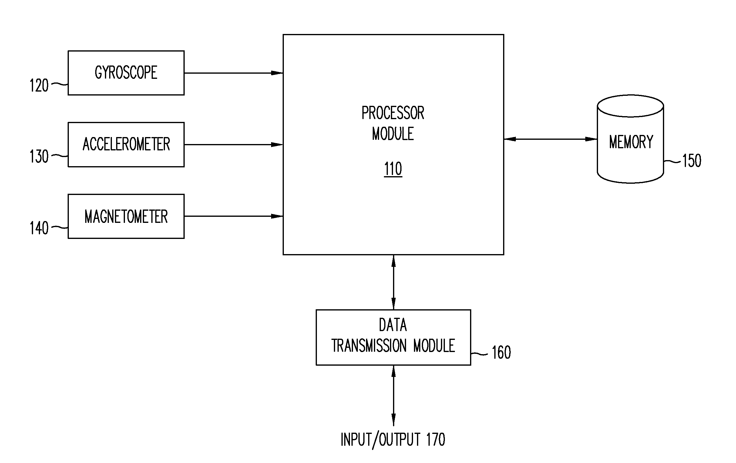
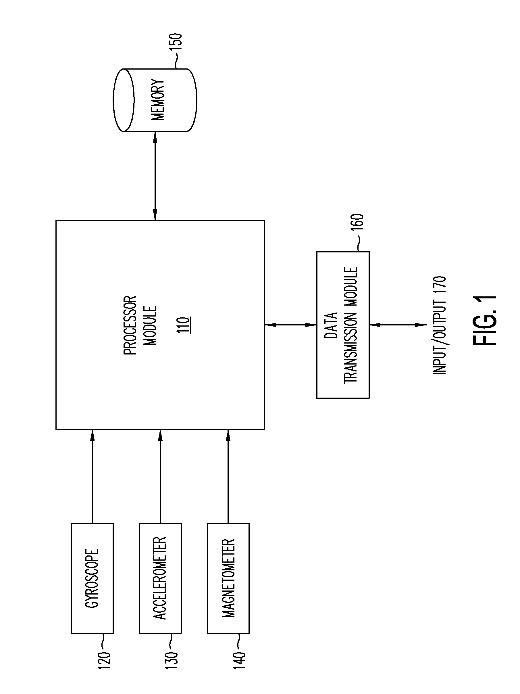
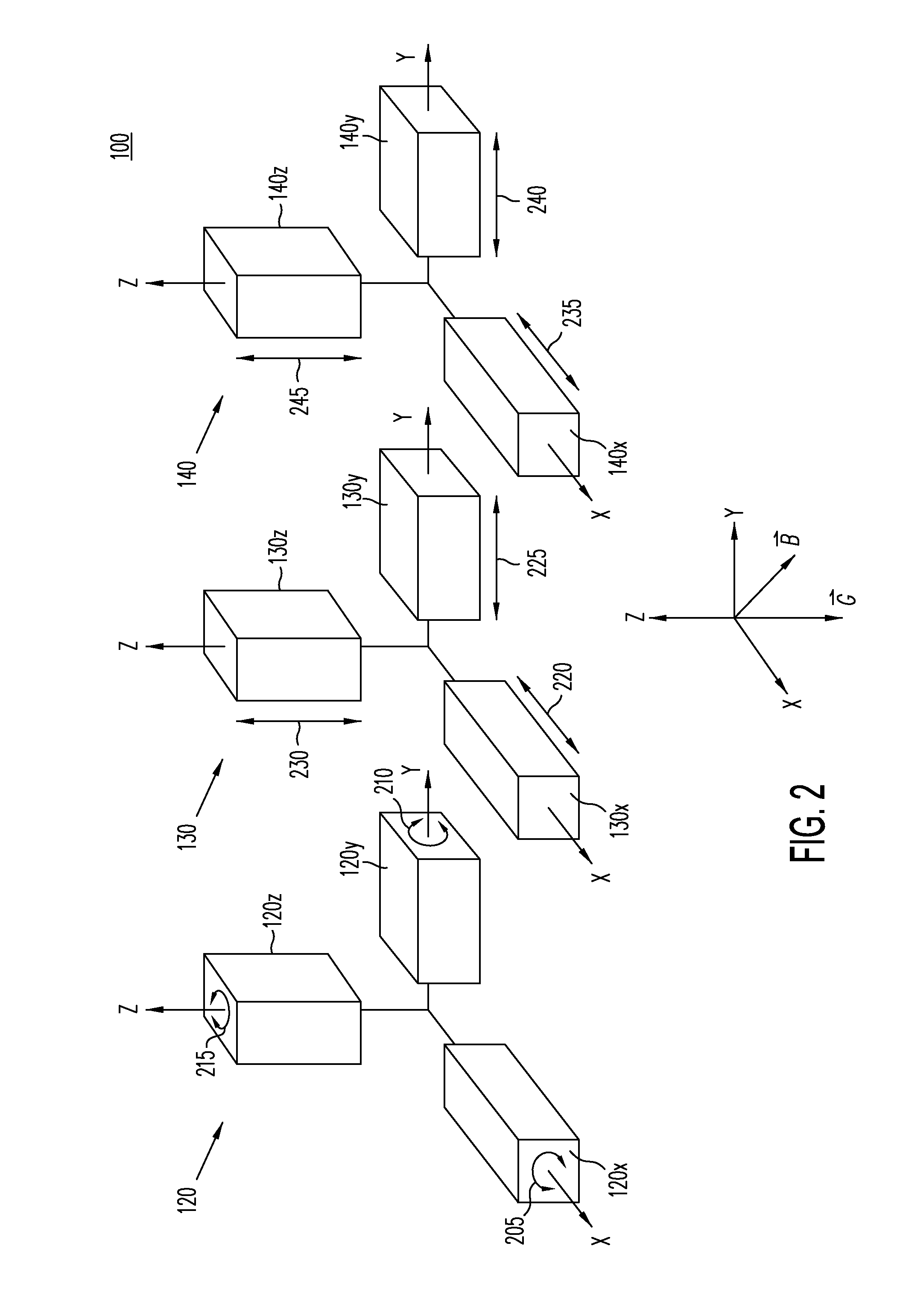
[0015]Embodiments of the present invention provide a mechanism by which a MEMS gyroscope sensor can be calibrated or recalibrated using data gathered from other sensors in a system incorporating the MEMS gyroscope sensor. In one example, data gathered from an accelerometer and a magnetometer that are in a fixed orientation relative to the gyroscope is used to calculate changes in orientation of a system embodying all of the sensors. A constant acceleration vector (e.g., gravity) measured by the accelerometer and a constant magnetic vector (e.g., the Earth's magnetic field) measured by the magnetometer are used as reference vectors in a solution to Wahba's problem to calculate a rotation matrix providing the system's orientation with respect to those two constant vectors. By comparing changes in orientation from one measurement time to the next measurement time, measured rates of angular change can be calculated. The measured rates of angular change can be used along with observed gy...


PUM


Abstract

A mechanism by which a MEMS gyroscope sensor can be calibrated using data gathered from other sensors in a system incorporating the MEMS gyroscope sensor is provided. Data gathered from an accelerometer and a magnetometer in fixed orientation relative to the gyroscope is used to calculate changes in orientation of a system. A constant acceleration vector measured by the accelerometer and a constant magnetic vector measured by the magnetometer are used as reference vectors in a solution to Wahba's problem to calculate a rotation matrix providing the system's orientation with respect to those two constant vectors. By comparing changes in orientation from one time to a next time, measured rates of angular change can be calculated. The measured rates of angular change can be used along with observed gyroscope rates of angular change as input to a linear regression algorithm, which can be used to compute gyroscope trim parameters.

Description

BACKGROUND[0001]1. Field[0002]This disclosure relates generally to sensor devices, and more specifically, to using rotational data acquired from an accelerometer and a magnetometer in a system to calibrate a gyroscope sensor in the system.[0003]2. Related Art[0004]Recent trends in consumer electronic devices include addition of a variety of motion and positional sensors in such devices. These sensors include accelerometers to measure device acceleration or position with regard to gravity or other acceleration forces, magnetometers to measure device orientation to a magnetic field, and gyroscopes to determine angular velocity of the device for a variety of applications. Inclusion and intelligent use of multiple types of sensors has been called “sensor fusion.” Useful application of sensor fusion involves accurate readings from all the sensors, and importantly from the gyroscope.[0005]Gyroscope sensors used in the devices discussed above are typically microelectromechanical systems (M...

Claims


Application Information

Patent Timeline
Patent Type & Authority Applications(United States)
IPC IPC(8): G01C25/00
CPCG01C25/005
Inventor STANLEY, MICHAEL E.
Owner NXP USA INC
Why Eureka
Try Eureka