Method And Device For Using Hot Air To De-Ice The Leading Edges Of A Jet Aircraft

a jet aircraft and leading edge technology, applied in aircraft components, de-icing equipment, transportation and packaging, etc., can solve the problems of affecting the aerodynamics of the wings, affecting the airflow of the fan, and being particularly exposed to the formation of ice, so as to improve the flexibility of the known devices and reduce the temperature range of hot air.

Active Publication Date: 2014-07-24
AIRBUS OPERATIONS (SAS)
View PDF4 Cites 7 Cited by
  • Summary
  • Abstract
  • Description
  • Claims
  • Application Information

AI Technical Summary

Benefits of technology

[0022]An aspect of the invention thus makes it possible to appreciably low the temperature range of the hot air supplied to these leading edges while at the same time ensuring that the minimum de-icing temperature is achieved under all engine operating conditions.
[0023]Further, the device according to an embodiment of the invention improves the flexibility of the known devices that use hot air for de-icing.
[0024]According to other features of the method according to an aspect of the invention, the plan is to bleed from the at least one engine hot air which, under maximum power operating conditions of the at least one engine, is at a temperature higher than or equal to the minimum de-icing temperature but low enough not to damage aircraft structural elements made of composite material.

Problems solved by technology

These leading edges are particularly exposed to the formation of ice under unfavourable temperature and humidity conditions.
The formation of ice on the lip of the air inlet cowl is liable to alter the aerodynamics in this inlet and thus disturb the passage of air towards the fan of the engine.
The formation of ice on the leading edges of the wings is also liable to adversely affect the aerodynamics of the wings by increasing their drag and reducing their lift.
Now, a temperature as high as this is incompatible with the composite materials increasingly used in an attempt to reduce the weight of the aircraft.
This entails the addition of protective elements (refer for example to Patent Application FR 2823533) which therefore represent an undesirable additional weight and make the structure more complicated.

Method used


Image

  • Method And Device For Using Hot Air To De-Ice The Leading Edges Of A Jet Aircraft
  • Method And Device For Using Hot Air To De-Ice The Leading Edges Of A Jet Aircraft
  • Method And Device For Using Hot Air To De-Ice The Leading Edges Of A Jet Aircraft

Examples


Embodiment Construction

[0049]In the figures, elements which are identical or equivalent will bear the same reference signs.

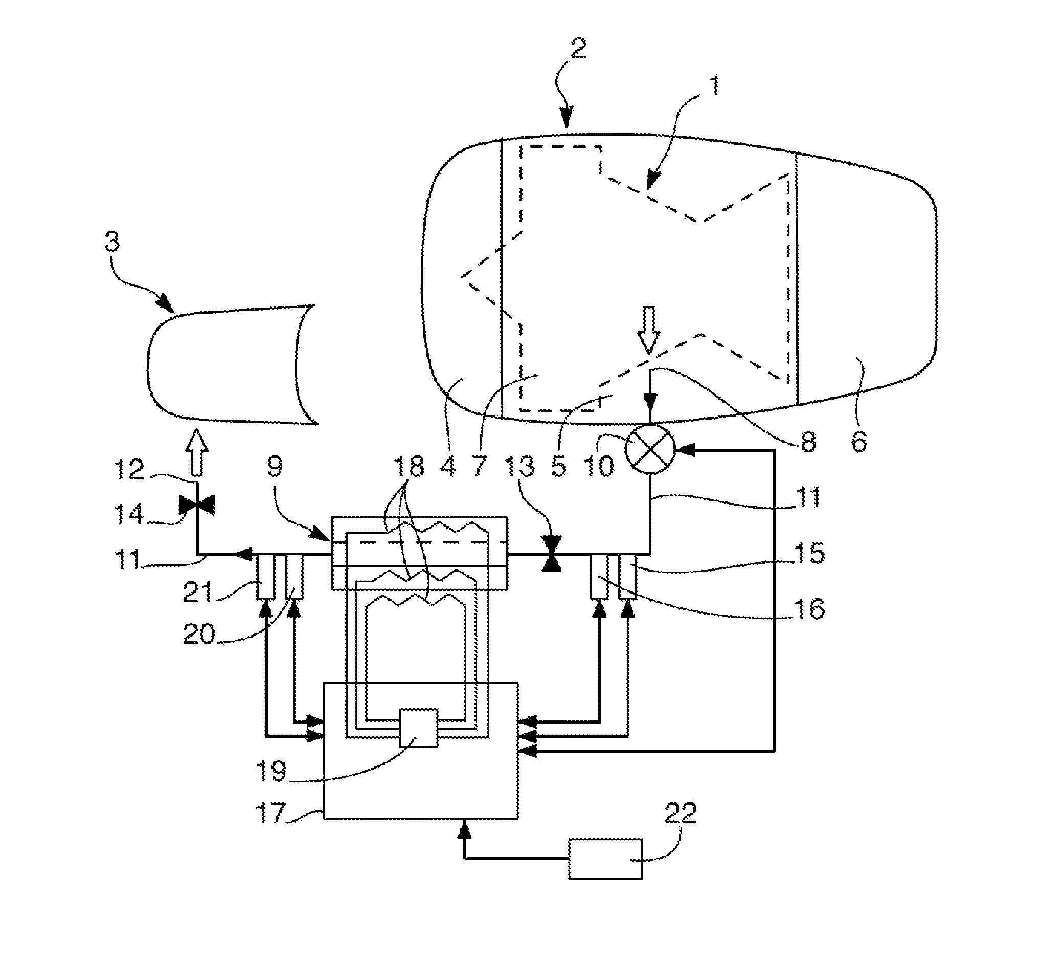
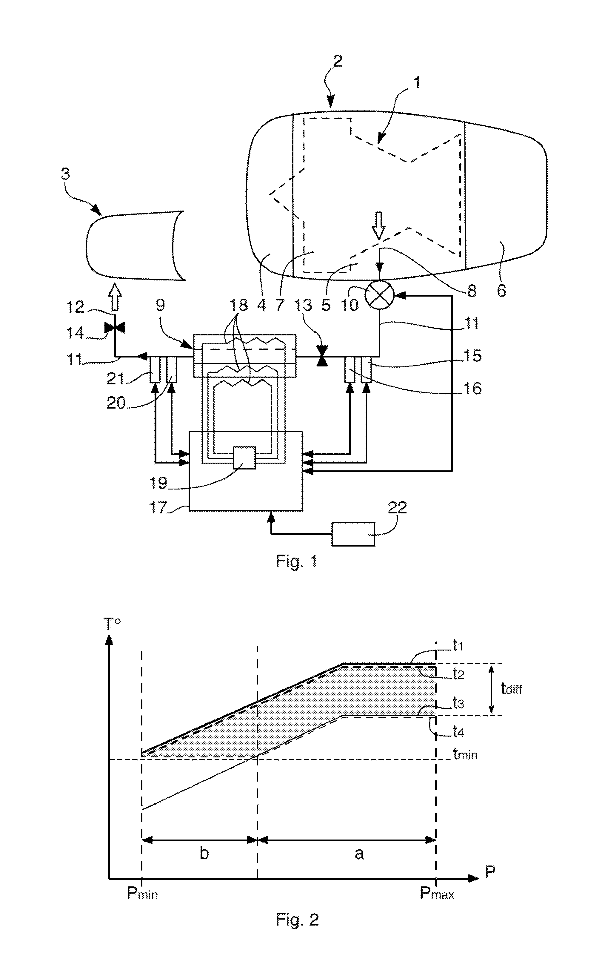
[0050]FIG. 1 schematically shows the hot air de-icing device according to an embodiment of the invention.

[0051]The hot air bled from a jet engine 1 is symbolized by an arrow in FIG. 1. The jet engine 1 is housed in a nacelle 2 borne by the fuselage of an aircraft (not illustrated in the figures).

[0052]FIG. 1 shows just one leading edge, namely a lip 3 of an air inlet cowl 4 followed by a central cowl 5 surrounding the engine 1, and finally a jet pipe cowl 6.

[0053]The hot air is bled under pressure from a stage (not depicted) of a compressor 7 positioned upstream of the engine 1. The hot air is bled by an inlet 8 of a hot air circulation circuit 9 passing through a flow regulating valve 10 which also acts as an isolation valve so that the flow can be switched on and off according to the need for a supply of hot air.

[0054]The pressurized hot air passes along the ducts 11 of the circulat...


PUM


Abstract

A de-icing device includes a hot air circuit including an inlet for hot air bled from an engine, and a duct connecting the inlet to an outlet of the circuit which opens towards the leading edge. The device also includes electrical heating means associated with the duct, and control means for controlling the heating means connected to detection means that detect the temperature of the hot air downstream of the heating means and are able to activate these if the detected temperature of the bled air is below a value corresponding to a minimum temperature required for de-icing, increased by a predetermined margin. The range of temperatures of the hot air supplied to the leading edge is lowered overall, whereas the minimum de-icing temperature is assured. Composite materials can be used near the leading edge without being damaged.

Description

TECHNICAL FIELD[0001]The present invention relates to a method and a device for using hot air for de-icing the leading edges of a jet aircraft.BACKGROUND OF THE INVENTION[0002]The leading edges of a jet plane consist mainly of the lip at the front end of the air inlet cowl of the jet engines and the slat formed by the forward edge of each wing. These leading edges are particularly exposed to the formation of ice under unfavourable temperature and humidity conditions.[0003]The formation of ice on the lip of the air inlet cowl is liable to alter the aerodynamics in this inlet and thus disturb the passage of air towards the fan of the engine.[0004]The formation of ice on the leading edges of the wings is also liable to adversely affect the aerodynamics of the wings by increasing their drag and reducing their lift.[0005]As a result, it is necessary to make provision for de-icing these leading edges if need be.[0006]One very commonplace solution is to use hot air bled from a compressor s...

Claims


Application Information

Patent Timeline
Patent Type & Authority Applications(United States)
IPC IPC(8): B64D15/04
CPCB64D15/04
Inventor CHENE, GILLES
Owner AIRBUS OPERATIONS (SAS)
Why Eureka
Try Eureka