Wheel sensor

A wheel sensor and giant magnetoresistive sensor technology, which is applied in railway car body parts, vehicle route interaction equipment, railway signal and safety, etc. and other problems, to achieve the effect of good detection direction, convenient installation and high sensitivity

Inactive Publication Date: 2008-11-05
HARBIN INST OF TECH
View PDF0 Cites 3 Cited by
  • Summary
  • Abstract
  • Description
  • Claims
  • Application Information

AI Technical Summary

Problems solved by technology

The potential difference is related to the change of the external magnetic field. When the locomotive wheel passes the surface of the Hall component, the change of the magnetic field decreases rapidly relative to the increase of the detection distance. Usually the maximum distance detected by the Hall sensor is about 10mm, and the induction signal varies with temperature. The change is obvious, and the detection baseline is very unstable; the electromagnetic sensor includes two coils for sending and receiving. After a certain AC excitation signal is passed through the sending coil, the sending coil and the receiving coil generate two magnetic fluxes. When the wheel passes the sensor, When the magnetic flux on the two coils changes, the voltage signal of the shaft counter will be induced on the receiving coil. Compared with the Hall sensor, this type of sensor has a larger detection distance, but the excitation coil and the receiving coil of the electromagnetic sensor are also It is easily disturbed by temperature. The general operating temperature range of the system is -25°C-70°C. The volume of the sensor is relatively large, so the application in cold areas is limited, and the scope of use has certain limitations.
The shell of this type of sensor is usually made of plastic shell. The structural strength of the plastic shell is poorer than that of the metal shell. It is usually used for a long time under low temperature and high stability conditions. The plastic shell is also easy to become brittle. It is difficult to adapt to the need to replace the sensor shell regularly. The harsh working environment of the railway
Limit the promotion and application of this type of sensor

Method used


Image

  • Wheel sensor
  • Wheel sensor
  • Wheel sensor

Examples


Embodiment 1

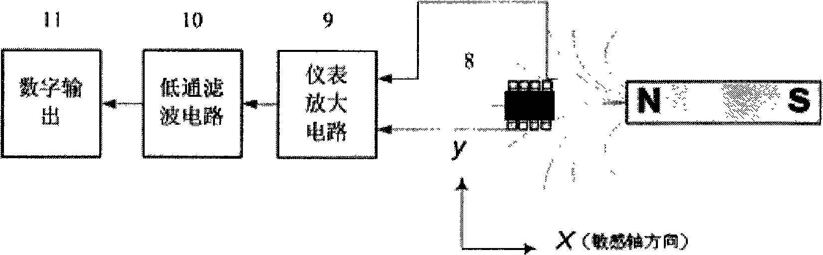
[0019] Embodiment 1: It is used as a wheel sensor. In this embodiment, a giant magnetoresistive chip is used as the core sensing element, and the detection of the wheel is completed in cooperation with the peripheral signal processing circuit. image 3 It is a block diagram of a typical circuit detection principle of a wheel sensor. The giant magnetoresistive sensor includes a bias magnetic field, a giant magnetoresistive chip 8 electrically connected in sequence, an instrument amplifier 9, a digital comparator 10, and a low-pass filter 11. The N pole of the bias magnetic field corresponds to Giant magnetoresistive chip 8 is arranged, and instrument amplifier 9 adopts AD620 instrument amplifier in the present embodiment, and low-pass filter 11 adopts active second-order low-pass filter, and when the external magnetic field changes, the resistance of Wheatstone bridge changes. The weak signal output by the bridge is sent to the AD620 instrumentation amplifier, filtered by an act...

Embodiment 2

[0020] Embodiment 2: Used as an axle counting sensor. In the application of this embodiment, two giant magnetoresistive sensors are used as a group, and the microprocessor 14 is used as an axle counting sensor. The circuit diagram of the system is as follows: Figure 4 As shown, the two sensors are respectively connected to the interrupt I / O ports of the microprocessor 14, and the direction of the train is judged according to the time sequence when the I / O port of the microprocessor 14 enters the interrupt. Cooperating with the microprocessor, the sensor has the ability to identify the vehicle type, and can judge whether the vehicle or the locomotive passes above the sensor. In this embodiment, when the axle counting device is connected to the microprocessor, it may also be one or more sensors. The housing of the sensor is made of aluminum material, which improves the stability of the whole system.


PUM


Abstract

The invention provides a wheel sensor, which comprises a fixed bracket and a giant magneto resistive sensor. The giant magneto resistive sensor comprises a bias magnetic field, a signal conditioning circuit and a giant magneto resistive chip; the signal conditioning circuit comprises an instrument amplifier, a digital comparator and a low-pass filter which are electrically connected with each other sequentially; the instrument amplifier is connected with the giant magneto resistive chip; the N-pole of the bias magnetic field is arranged correspondingly to the giant magneto resistive chip. The wheel sensor adopts the design of giant magneto resistive sensor, can be used for detecting the train wheels, effectively reduces the volume of the system, improves the working temperature range of the system and the stability of the operation of the system, and can be excellently applicable for the working environment of railway situations.

Description

(1) Technical field [0001] The invention relates to a wheel device for identifying railway locomotives, in particular to a giant magnetoresistive wheel sensor. (2) Background technology [0002] At present, the commonly used wheel detection devices in China mainly use Hall devices and electromagnetic sensors. The Hall sensor is that when the current flows through the conductor perpendicular to the direction of the external magnetic field, a certain amount of noise will be generated on both sides of the conductor perpendicular to the direction of the current and the magnetic field. Potential difference. The potential difference is related to the change of the external magnetic field. When the locomotive wheel passes the surface of the Hall component, the change of the magnetic field decreases rapidly relative to the increase of the detection distance. Usually the maximum distance detected by the Hall sensor is about 10mm, and the induction signal varies with temperature. The...

Claims


Application Information

Patent Timeline
Patent Type & Authority Applications(China)
IPC IPC(8): B61L1/16
Inventor 刘晓为张海峰唐佳禄尹亮刘广新
Owner HARBIN INST OF TECH
Why Eureka
Try Eureka