Charging and discharging device

a charging and discharging device technology, applied in the direction of battery/fuel cell control arrangement, battery/cell propulsion, battery/cell control arrangement, etc., can solve the problems of high withstand voltage capacitors, small scale of the entire device, and cost, so as to reduce electric power transmission loss and increase charging efficiency

Active Publication Date: 2014-07-24
HONDA MOTOR CO LTD
View PDF2 Cites 11 Cited by
  • Summary
  • Abstract
  • Description
  • Claims
  • Application Information

AI Technical Summary

Benefits of technology

[0018]According to the present invention, when one battery module is discharged and another battery module is charged, charging efficiency is increased by way of full-wave rectification.
[0019]The control terminals or the other control terminals are connected to the isolating transformer through inductors that are connected in series with the capacitors. If one battery module is discharged while another battery module is charged, an electric path may comprise a series resonant path, which is made up of the series-connected capacitors and inductors. AC generating circuits, which exhibit a series resonant frequency equivalent to that of the series resonant path, are effective to reduce electric power transmission loss.

Problems solved by technology

However, since high withstand voltage capacitors are expensive and constituted by large circuit components, an obstacle is presented with respect to efforts to make the entire device smaller in scale and lower in cost, including efforts to maintain a creepage distance on the board.

Method used


Image

  • Charging and discharging device
  • Charging and discharging device
  • Charging and discharging device

Examples


Embodiment Construction

[0059]Charging and discharging devices according to embodiments of the present invention will be described below under respective topics given in the following order with reference to the drawings.

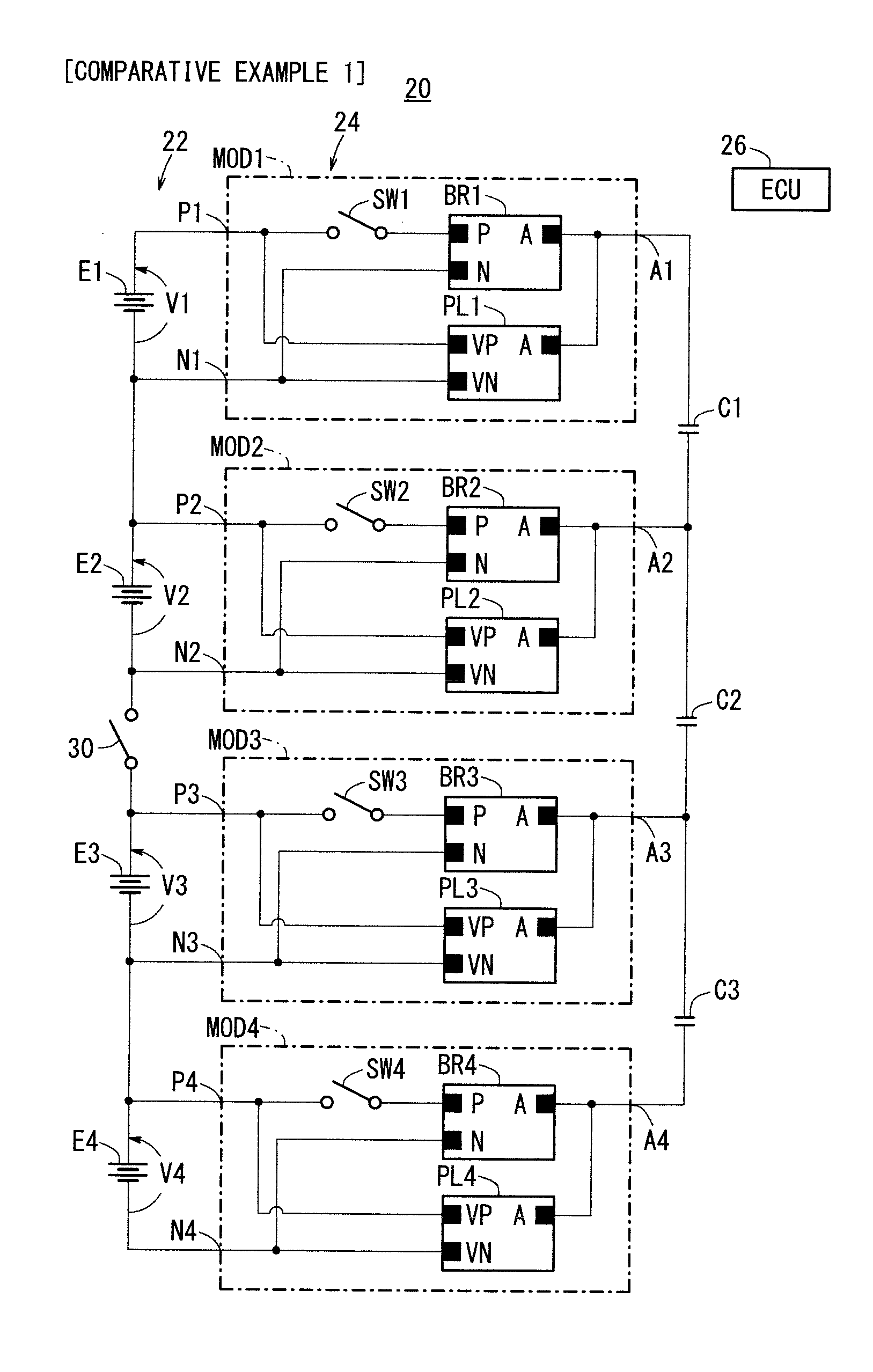
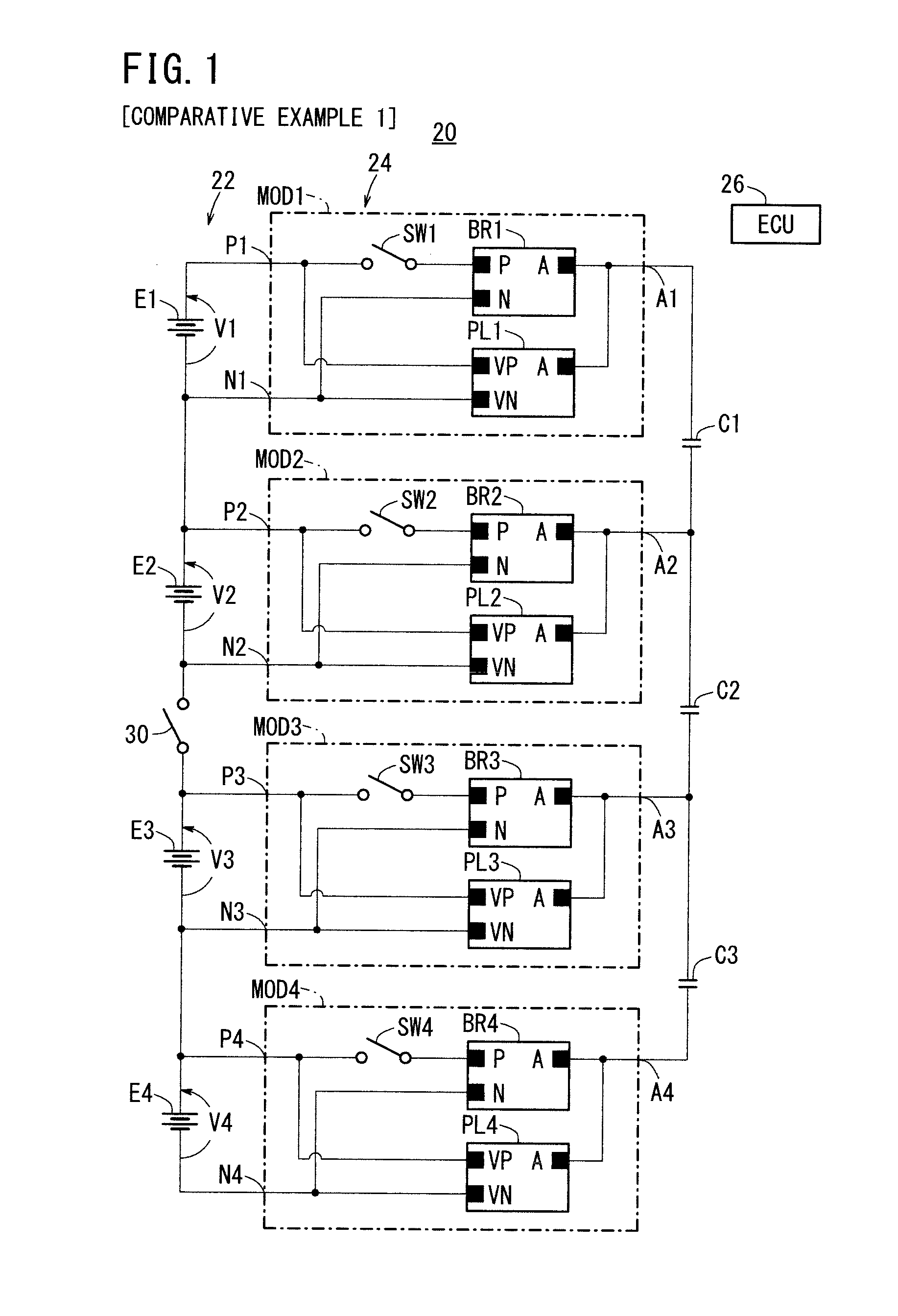
1. Description of Arrangement and Operations of Comparative Example 1;

2. Description of Arrangement and Operations of Inventive Example 1 and Modifications;

3. Description of Arrangement and Operations of Comparative Example 2;

4. Description of Arrangement and Operations of Inventive Example 2 and Modifications;

5. Description of Arrangement and Operations of Comparative Example 3;

6. Description of Arrangement and Operations of Inventive Example 3.

[0060]For the sake of brevity and for facilitating understanding of the present invention, in the drawings below, it will be assumed that a battery assembly, which includes a number of series-connected battery modules and has several hundred volts, for example, applied thereacross, is made up of four series-connected battery modules.

1. Description ...


PUM


Abstract

Provided is a charging and discharging device that does not need to use a high voltage capacitor even if a shielding switch is provided in an assembled battery for the sake of convenience of maintenance, and the like. The charging and discharging device includes: capacitors for connecting control terminals of adjacent circuit blocks, the shielding switch interposed between the adjacent battery modules, and a transformer interposed between the control terminals corresponding to the adjacent battery modules.

Description

TECHNICAL FIELD[0001]The present invention relates to a charging and discharging device for independently adjusting the charge levels of battery modules of a battery assembly, which is made up of a plurality of battery modules connected in series, each of the battery modules comprising at least one cell as a secondary cell.BACKGROUND ART[0002]Recently, vehicles propelled by at least the drive power of a motor, such as electric vehicles (EV), hybrid electric vehicles (HEV), plug-in hybrid electric vehicles (PHEV), fuel cell vehicles (FCV), or the like, have a battery assembly housed in a battery box, which serves as an electric power source for an electric motor. The battery assembly is made up of a plurality of series-connected battery modules, each of which comprises at least one cell as a secondary cell that is chargeable and dischargeable. The electric motor is energized by a high DC voltage generated by the battery assembly and which is applied through an inverter.[0003]The seri...

Claims


Application Information

Patent Timeline
Patent Type & Authority Applications(United States)
IPC IPC(8): B60L11/18H02J7/02
CPCB60L11/1811B60L11/18B60L2240/547B60L2240/549B60L58/22H01M10/4207H01M2010/4271H01M2220/20H02J7/0018Y02E60/10Y02T10/70B60L50/50Y02T10/7072Y02T90/12Y02T90/14
Inventor OHNUKI, YASUMICHI
Owner HONDA MOTOR CO LTD
Why Eureka
Try Eureka