
Zero-voltage-switching contour based outphasing power amplifier

a power amplifier and contour technology, applied in amplifiers, amplifiers with semiconductor devices/discharge tubes, amplifiers, etc., can solve the problems of poor efficiency at backed-off power levels, envelope tracking pas suffer from supply regulator bandwidth and efficiency problems, transformer combiner based pa is limited, etc., to achieve wide dynamic range and wide dynamic range

Inactive Publication Date: 2014-07-24
RGT UNIV OF CALIFORNIA
View PDF5 Cites 12 Cited by
  • Summary
  • Abstract
  • Description
  • Claims
  • Application Information

AI Technical Summary

Benefits of technology

The present invention is a power amplifier (PA) that uses an outphasing zero voltage switching (ZVS) architecture to achieve wide dynamic range. The invention includes two separate PAs that are connected to a load, and the PAs are controlled using variable capacitors that are controlled based on the duty cycle of the input drive signals. The invention has advantages over previous amplifier systems and provides a wider dynamic range of output signals.

Problems solved by technology

Linear power amplifiers (PAs), such as class A, B, and AB amplifiers, are biased for peak output power and consequently suffer from poor efficiency at backed-off power levels.
However, a transformer combiner based PA is limited by die size constraints, and envelope tracking PAs suffer from supply regulator bandwidth and efficiency problems.
Yet, these architectures suffer from supply regulator inefficiency, particularly while handling wide bandwidth envelope variations.
Recently developed digital PA architectures, such as the digital envelope modulator and the switching mixer PA architectures, all suffer from efficiency degradation at backed-off power levels.
Duty cycle modulation and dynamic load modulation, such as used for class-E PAs, can achieve high peak efficiency but results in poor efficiency at low output power levels.
In fact, class-E PAs operate sub-optimally at low output power levels when zero voltage switching (ZVS) conditions are not satisfied, thus resulting in significant losses and poor efficiency.

Method used


Image

  • Zero-voltage-switching contour based outphasing power amplifier
  • Zero-voltage-switching contour based outphasing power amplifier
  • Zero-voltage-switching contour based outphasing power amplifier

Examples


Embodiment Construction

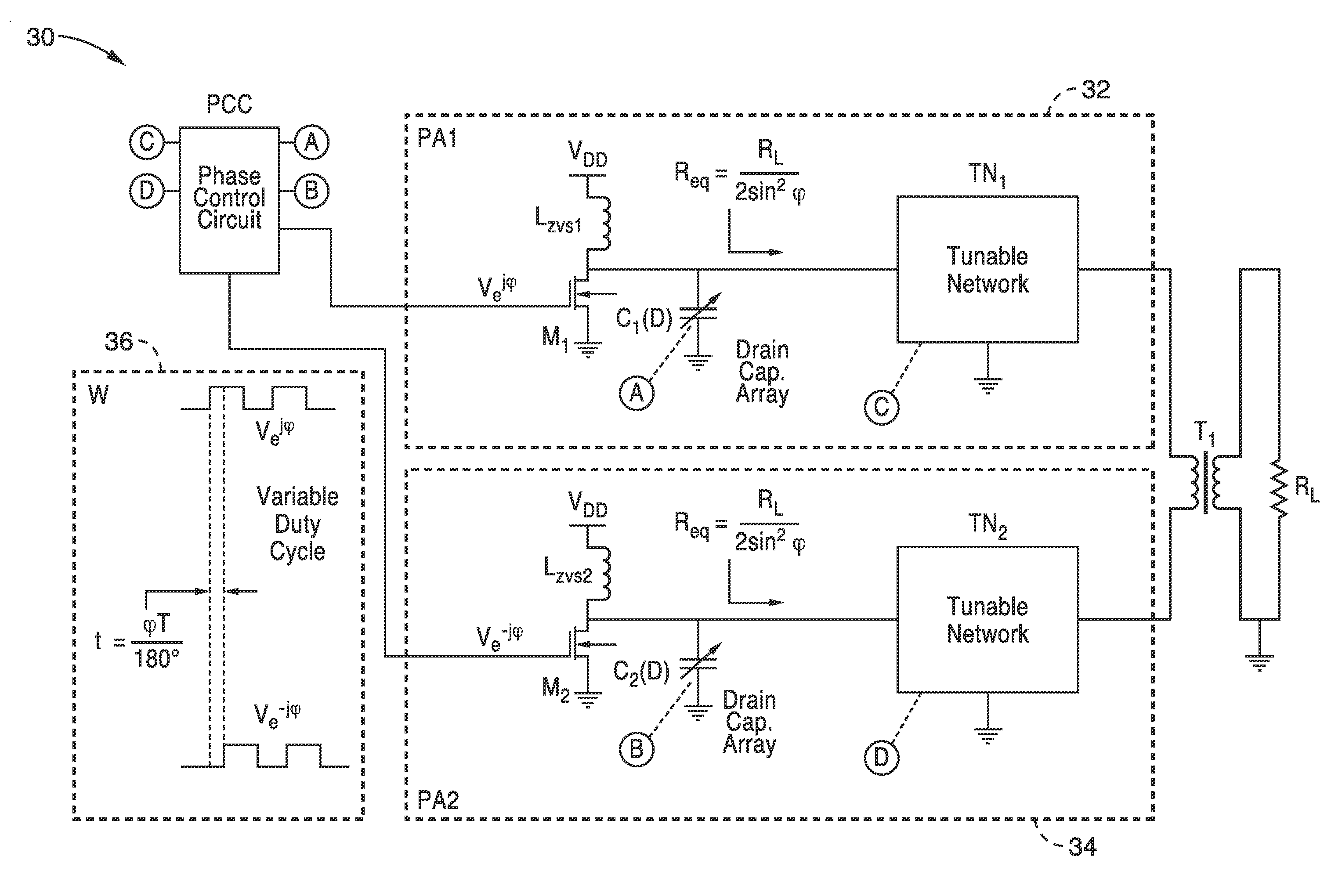
[0019]Our inventive outphasing ZVS contour based power amplifier (PA) architecture is based on the ZVS contour based PA. In a ZVS contour based PA, peak efficiency is maintained even under back-off conditions by a circuit configuration with select component values, such that ZVS conditions are met at varying duty cycles. Specifically, this involves varying the drain capacitance C and the equivalent resistance Req for a fixed zero voltage switching transistor drain inductance Lzvs along with duty cycle D according to the following relation:

ω0LZVSReq=g1(D)andω0CReq=g2(D)

in which g1(D) and g2(D) are determined, such as analytically or empirically to ensure ZVS switching. The resultant output power varies with the duty cycle D according to the following relation:

Pout(D)=g3(D)·VDD2Req

The functions g1(D) and g2(D) and g3 (D) can be found as solutions to a set of equations that can be analytically derived, or empirically determined as described in a later section.

[0020]Conventional class-E...


PUM


Abstract

A zero-voltage-switching contour based outphasing power amplifier having two class-E power amplifiers connected in an out-phasing architecture coupled on opposite sides of a load being driven. The pair of class-E power amplifiers receive separate digital drive signals with an amount of phase difference that is adjusted based on the load. Variable capacitor arrays are coupled in parallel on the class-E power amplifiers and controlled in response to system parameters including duty cycle of the input signal. Efficiency of the power amplifier is maintained despite variation in output loading.

Description

CROSS-REFERENCE TO RELATED APPLICATIONS[0001]This application is a 35 U.S.C. §111(a) continuation of PCT international application number PCT / US2012 / 049075 filed on Jul. 31, 2012, incorporated herein by reference in its entirety, which claims priority to U.S. provisional patent application Ser. No. 61 / 513,625 filed on Jul. 31, 2011, incorporated herein by reference in its entirety.[0002]The above-referenced PCT international application was published as PCT International Publication No. WO 2013 / 019819 on Feb. 7, 2013 and republished on Jul. 4, 2013, which publications are incorporated herein by reference in their entireties.STATEMENT REGARDING FEDERALLY SPONSORED RESEARCH OR DEVELOPMENT[0003]This invention was made with Government support under Grant No. 0725785 awarded by the National Science Foundation. The Government has certain rights in the invention.INCORPORATION-BY-REFERENCE OF MATERIAL SUBMITTED ON A COMPACT DISC[0004]Not ApplicableNOTICE OF MATERIAL SUBJECT TO COPYRIGHT PRO...

Claims


Application Information

Patent Timeline
Patent Type & Authority Applications(United States)
IPC IPC(8): H03F3/217
CPCH03F3/2176H03F1/0294H03F1/3205H03F1/56H03F3/195H03F3/245H03F2200/378H03F2200/387
Inventor PAMARTI, SUDHAKARSINGHAL, NITESH
Owner RGT UNIV OF CALIFORNIA
Features
  • Generate Ideas
  • Intellectual Property
  • Life Sciences
  • Materials
  • Tech Scout
  • Unparalleled Data Quality
  • Higher Quality Content
  • 60% Fewer Hallucinations
Learn More