
In-cell touch screen and drive method thereof

a touch screen and in-cell technology, applied in the direction of electric digital data processing, instruments, computing, etc., can solve the problems of low signal noise ratio (snr) of the touch control, false touch, and insufficient time to be allocated in one scanning period, so as to avoid the effects of severe touch noise caused by tft charging, enhanced snr of the touch signal, and enhanced touch accuracy

Active Publication Date: 2014-07-24
SHANGHAI TIANMA MICRO ELECTRONICS CO LTD
View PDF4 Cites 21 Cited by
  • Summary
  • Abstract
  • Description
  • Claims
  • Application Information

AI Technical Summary

Benefits of technology

The present invention provides an In-cell touch screen and a method for driving it to solve the problem of low SNR for touch control and the occurrence of false touch in prior art. The method allows for enhanced accuracy of touch control and improved degree of satisfaction. The simultaneous drive method removes interference signals caused by TFT charging, thereby improving the SNR of touch signals and avoiding severe touch noises. This is achieved by extending the scanning periods of display drive and touch drive, and removing the original touch signals collected from sensing lines when any gate lines are applied with the gate drive signal. Overall, the technical effect of the invention is to improve touch accuracy and experience.

Problems solved by technology

Therefore, there may not be enough time to be allocated in one scanning period.
That is to say, the display drive scanning and the touch drive scanning are performed simultaneously in one scanning period, whereby the charging and discharging of the TFTs on the array substrate will be completed in the scanning period T. However, capacitive couplings may be generated from the charging and discharging of the TFTs and turn into noises that may affect the touch function and cause the problems of low signal noise ratio (SNR) for the touch control and even false touch.

Method used


Image

  • In-cell touch screen and drive method thereof
  • In-cell touch screen and drive method thereof
  • In-cell touch screen and drive method thereof

Examples


Embodiment Construction

[0049]Specific embodiments are described below. Although the invention will be described with reference to the exemplary embodiments thereof, the following exemplary embodiments and modifications do not restrict the invention.

[0050]Embodiments of the present invention provide a method for driving an In-cell touch screen. The structure of the In-cell touch screen will be explained at first for the purpose of convenience in explaining the method. The In-cell touch screen according to an embodiment of the invention includes an array substrate and a color film substrate disposed opposite to each other, wherein a touch function layer of the In-cell touch screen is integrated on the color film substrate.

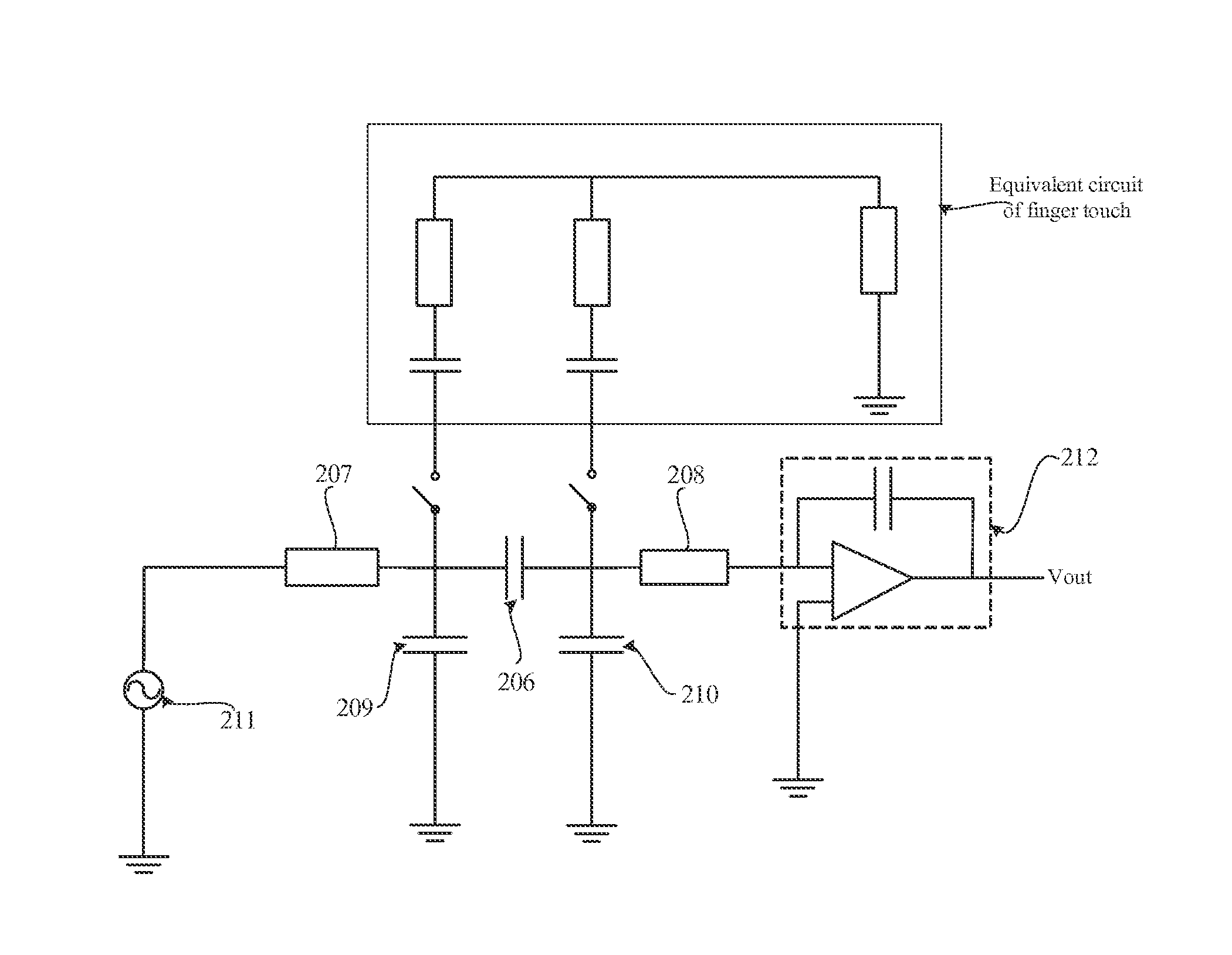
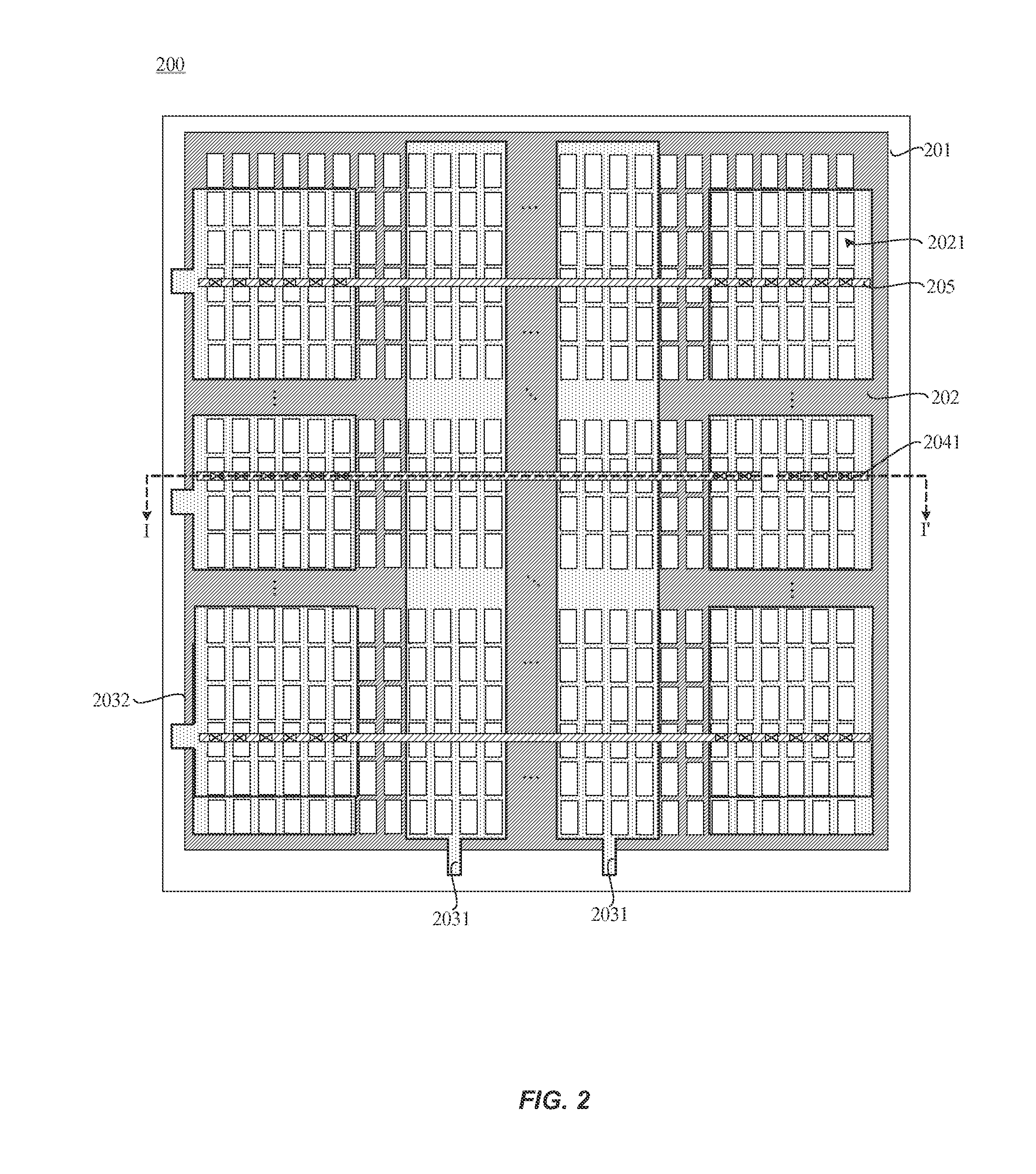
[0051]As shown in FIG. 2 and FIG. 3, the color film substrate 200 includes a transparent substrate 201, a black matrix layer 202 formed on the transparent substrate 201, a conductive layer formed on the black matrix layer 202, and an color-resist insulating layer 204 formed on the conducti...


PUM


Abstract

An In-cell touch screen and a method for driving the same includes: concurrently providing a plurality of gate drive signals to the plurality of gate lines line by line and a plurality of touch drive signals to the plurality of drive lines line by line, collecting original touch signals from the plurality of sensing lines line by line; when collecting is performed on a sensing line and any gate line covered by the sensing line is supplied with a gate drive signal, defining the original touch signals collected from a sensing line as interference signals; and removing the interference signals from the original touch signals to obtain a valid touch signal.

Description

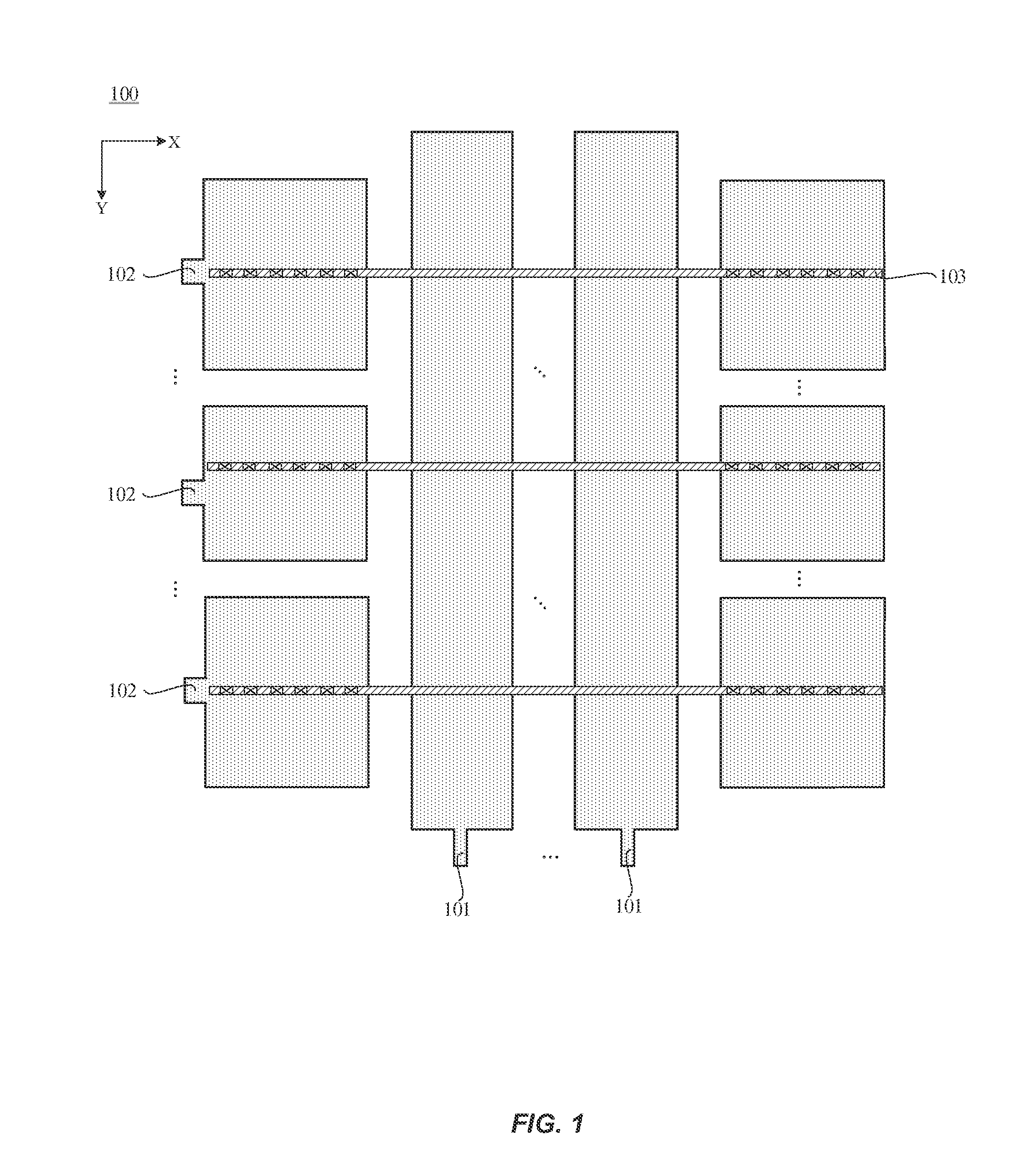
CROSS REFERENCE TO RELATED APPLICATIONS[0001]This application claims the benefit of priority to Chinese Patent Application No. 201310025238.5, filed with the Chinese Patent Office on Jan. 23, 2013 and entitled “IN-CELL TOUCH SCREEN AND DRIVE METHOD THEREOF”, the contents of which is incorporated herein by reference in its entirety.BACKGROUND OF THE INVENTION[0002]The In-cell touch screen is popular because the touch system can be integrated with the display screen so that the thickness of the whole liquid crystal display (LCD) can be reduced effectively and the manufacturing process can be simplified. LCD usually includes a color film substrate and an array substrate. In the In-cell touch screen, the touch system is usually disposed at the side of the color film substrate since the array substrate usually includes more circuit designs.[0003]As shown in FIG. 1, a touch layer 100 is integrated at the side of the color film substrate in the In-cell touch screen. The touch layer 100 inc...

Claims


Application Information

Patent Timeline
Patent Type & Authority Applications(United States)
IPC IPC(8): G06F3/044
CPCG06F3/044G06F3/0412G09G3/3648G06F3/0446G06F3/04166G06F3/0445G06F3/04184G06F3/0418
Inventor LU, FENGMA, JUN
Owner SHANGHAI TIANMA MICRO ELECTRONICS CO LTD
Learn More