

Heat sink for cooling of power semiconductor modules
a technology for semiconductor modules and heat sinks, which is applied in the direction of cooling/ventilation/heating modifications, semiconductor/solid-state device details, semiconductor devices, etc., and can solve problems such as degrading the operation of semiconductor devices
- Summary
- Abstract
- Description
- Claims
- Application Information
AI Technical Summary
Benefits of technology
Problems solved by technology
Method used
Image

Examples
Embodiment Construction
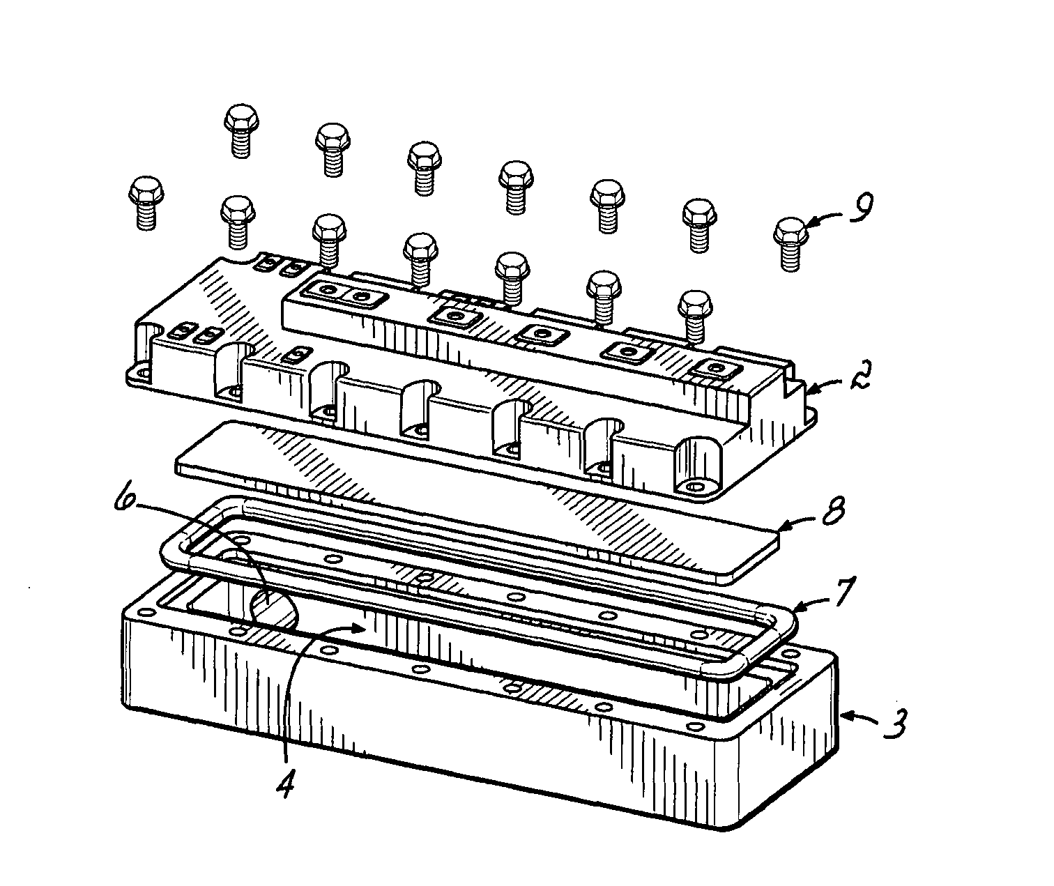
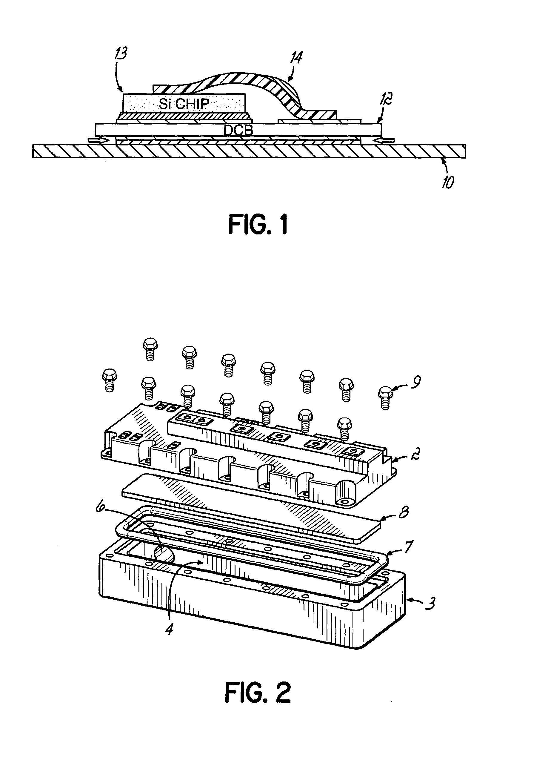
[0017]Aspects of the invention relates to a heat sink, especially for liquid cooling of power semiconductors modules. The power semiconductor module(s) are mounted on a first side of a base plate that, in turn, is mounted to a heat sink on a second side of the base plate. The heat sink includes a basin that holds coolant in thermal contact with the second side of the base plate to remove heat from the power semiconductor module. A sealed joint between the base plate and the heat sink is formed, such as by a gasket, to avoid leaks of the liquid coolant.
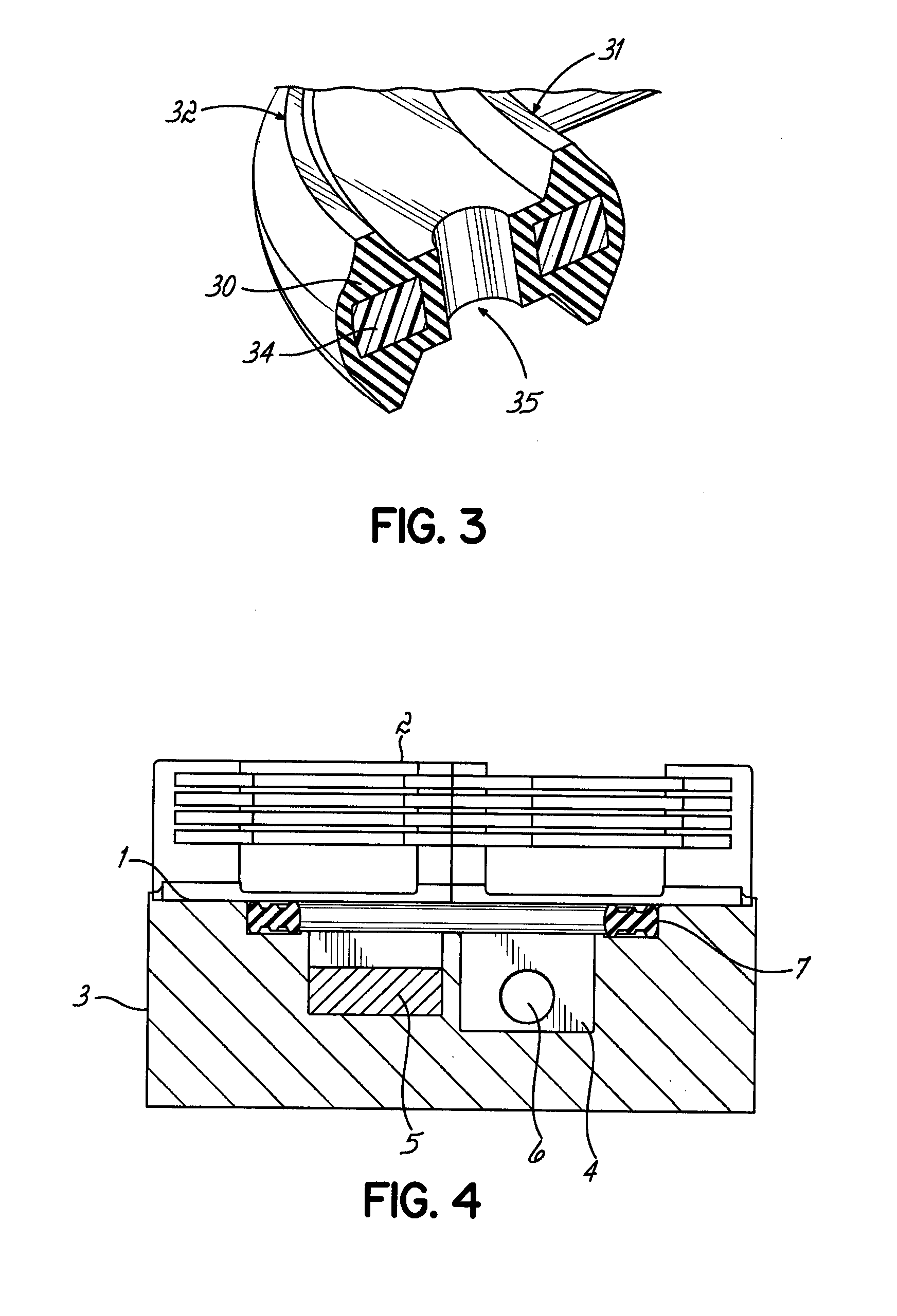
[0018]According to an aspect of the invention, a surface of the heat sink that surrounds the basin and that faces the base plate when mounted thereto, includes a contact surface that is sloped toward the basin. The applicant has appreciated that fasteners used to hold the heat sink to the base plate may cause warping of the base plate when the fasteners are executed.
[0019]According to some embodiments, the heat sink may be connected to...
PUM
 Abstract
Description
Claims
Application Information