Vacuum box, belt filter, methods for servicing a vacuum belt filter, method for liquid-solid separation of a slurry, and filter element

a vacuum box and filter element technology, applied in the direction of filtration separation, separation process, chemistry apparatus and processes, etc., can solve the problem of low energy consumption and achieve the effect of low energy cost, simple construction and convenient flow

Active Publication Date: 2020-05-19
METSO OUTOTEC (FINLAND) OY
View PDF22 Cites 2 Cited by
  • Summary
  • Abstract
  • Description
  • Claims
  • Application Information

AI Technical Summary

Benefits of technology

[0003]It is an object of the present invention to provide a new type of vacuum belt filter and a new method for liquid-solid separation, said belt filter having a simple construction enabling liquid-solid separation with low energy consumption and having long service interval. It is further an object of the present invention to provide a filter element and a vacuum box for building the vacuum belt filter of the invention, and a method for servicing the vacuum belt filter of the invention, the vacuum box being capable of maintaining an underpressure within its inside space without being connected to a vacuum source. With the expression vacuum source is here meant a source capable of creating into the vacuum boxes a pressure which is below the surrounding pressure, typically below the atmospheric pressure of 1 bar.
[0005]A capillary filter refers to a filter the structure and / or the material of which enables a certain amount of liquid, such as water, to be retained in the filter by a capillary action despite a differential pressure formed by a gas surrounding the filter. The liquid may be retained in the micro-pores provided in the filter. A capillary filter enables the liquid to be filtered to easily flow through the filter, but when all free liquid, such as the free liquid entering the filter has passed through the filter, the remaining liquid retained in the filter by the capillary action prevents flow of gas, such as air, through the wet filter.
[0006]A major advantage of the vacuum belt filter, the vacuum box and the filter element of the invention is that they enable liquid-solid separation at low energy costs and the servicing interval of the belt filter is long, because the life-time of the filters of the belt filter is long. The vacuum box of the vacuum belt filter has a simple construction making it, and also the belt filter, easy to build. The belt filter can be operated with an extremely small vacuum pump this meaning essential energy savings. Despite this, a high underpressure, i.e. a low absolute pressure, can be created within the vacuum box. Service and repair of the belt filter is easy. The vacuum boxes can be replaced individually without a need to replace all the vacuum boxes if one or more of the vacuum boxes is a need of repair. Filtration can continue within the vacuum boxes without continuous vacuum feed. Moreover, the vacuum belt filter according to invention is suitable for long cake drying periods because the length of the belt can be selected freely. In the vacuum belt filter according to invention a total filter media is divided into a large number of vacuum boxes each working as an individual dewatering element. In the vacuum belt filter according to invention the differential pressure responsible for the dewatering is effective over the whole length of the belt from vacuum station to discharge station. This is the most efficient way of achieving lowest cake moisture. In the vacuum belt filter according to invention leakage of air between the filter media and the vacuum box does not appear and a differential pressure over the filter cake is maintained. Hence, as the vacuum source does not have to compensate for leakage, the dewatering of the filter cake is efficient and energy consumption is low.

Problems solved by technology

Hence, as the vacuum source does not have to compensate for leakage, the dewatering of the filter cake is efficient and energy consumption is low.

Method used


Image

  • Vacuum box, belt filter, methods for servicing a vacuum belt filter, method for liquid-solid separation of a slurry, and filter element
  • Vacuum box, belt filter, methods for servicing a vacuum belt filter, method for liquid-solid separation of a slurry, and filter element
  • Vacuum box, belt filter, methods for servicing a vacuum belt filter, method for liquid-solid separation of a slurry, and filter element

Examples


second embodiment

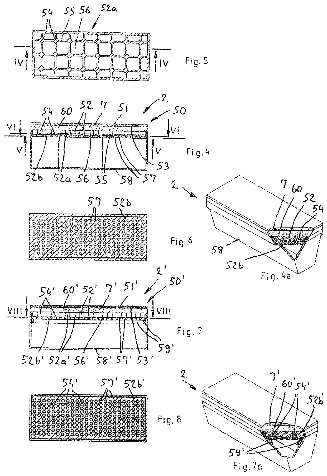
[0037]FIGS. 7a, 7 and 8 illustrate the filter element. In FIGS. 7a, 7 and 8 have been used similar reference numerals as in FIGS. 4 to 6 for corresponding components. The filter element 50′ of FIGS. 7a, 7 and 8 differs from the embodiment shown in FIG. 4a and FIGS. 4-6 in that the support element 52a′ is fastened not only to the intermediate layer 60, but also to the support element 52b′, which thus is part of the support structure 52′ and part of filter element 50′. Connectors, c.f. connectors 55 like those in FIG. 5, are not needed, because support element 52b′ connects the support parts 54′. Support element 52b′ is thus also a connecting means. The fastening of the support element 52a′ to the support element 52b′ can be carried out by various manners (permanently e.g. by gluing, or detachably e.g. by snap fasteners) as appreciated by a person skilled in the art. The support element 52b′ of FIG. 8 comprises a multitude of holes 57′, like support element 52b of FIG. 6. The support ...

third embodiment

[0038]FIGS. 9 and 10 show the filter element 50″. A corner area of the filter element 50″ is shown opened in the figures—only to illustrate the construction of the filter element. In the embodiment of FIGS. 9 and 10 the capillary filter 7″ is supported by a support structure 52″ in the form of a honeycomb structure. The honeycomb structure comprises a multitude of spaced holes 58″ defined by walls 61″. The honeycomb structure can preferably be made of plastic, preferably thermoplastic. If the honeycomb structure is made of plastic, there is preferably an intermediate ceramic layer 60″ between the filter 7″ and the honeycomb structure as shown in FIGS. 9 and 10. The intermediate ceramic layer 60″ has a grit number of 40 to 300, preferably 40 to 180, more preferably 60-120 which grid values form a rough joining interface for attaching of the honeycomb structure to the capillary filter 7″. However, the honeycomb structure can alternatively be made of e.g. ceramic material. If the suppo...

fourth embodiment

[0039]FIGS. 11 and 12 show the filter element. The filter element 50′″ of FIGS. 11 and 12 differs from the filter element 50′″ of FIGS. 9 and 10 essentially in that the support structure 52″ is a compact piece of porous material, i.e. it does not comprise (macroscopic) holes, c.f. holes 58″ in FIG. 10. A corner of the filter element 50′″ is shown opened to illustrate this. The pore size of the compact piece is bigger than the pore size of the ceramic filter 7′″. The piece is preferably a ceramic brick preferably made of a highly porous material. Alternatively, a compact piece of plastic or a piece of porous metal can be used. The capillary filter 7′″ has been formed onto the brick preferably by spraying. The manufacturing of the filter element 50′″ comprises preferably compressing a raw material to a brick, burning the brick in an oven, spraying the brick with a ceramic membrane layer, and finally burning the brick with the membrane layer in an oven. The brick has a grit number of 4...


PUM

PropertyMeasurementUnit
pore sizeaaaaaaaaaa
atmospheric pressureaaaaaaaaaa
areaaaaaaaaaaa

Abstract

A vacuum belt filter including a belt with a plurality of vacuum boxes, filter means being arranged to the vacuum boxes, drive means for moving the belt, and a suction station for creating an underpressure to the vacuum boxes at the suction station. In order to enable liquid-solid separation at low energy costs and long service interval of the vacuum belt filter, the filter means is in the form of a capillary filter, each vacuum box being provided with such a filter and each vacuum box being provided with an outlet having a check valve enabling a fluid flow from the inside space of the vacuum box to the outside of the vacuum box for creating an underpressure in the vacuum box when the suction station is connected to the vacuum box.

Description

CROSS-REFERENCE TO RELATED APPLICATIONS[0001]This application is a National Phase Entry under 35 U.S.C. § 371 of PCT International Application No. PCT / FI2016 / 050768 filed Nov. 2, 2016, which claims the benefit of PCT International Patent Application No. PCT / FI2015 / 050756 filed Nov. 3, 2015, the disclosure of each of these applications are expressly incorporated herein by reference in their entirety.BACKGROUND OF THE INVENTION[0002]Filtration is a widely used process in which a solid-liquid mixture, such as a slurry or sludge, is forced against a filtering media, with the solids retaining on the filtering media and the liquid phase passing through. The present invention relates more precisely to a vacuum box and a vacuum belt filter. Vacuum belt filters are conveyor-type filters widely used in the dewatering of slurries. The invention relates further to servicing a vacuum belt filter and to a method for liquid-solid separation of slurry in a belt filter. The invention relates further...

Claims


Application Information

Patent Timeline
Patent Type & Authority Patents(United States)
IPC IPC(8): B01D33/00B01D33/056B01D33/15
CPCB01D33/056B01D33/0058B01D33/155B01D29/09B01D29/50B01D29/96B01D33/15B01D33/333
Inventor VÄNTTINEN, KARIILLI, MIKAEKBERG, BJARNE
Owner METSO OUTOTEC (FINLAND) OY
Why Eureka
Try Eureka