Container handling vehicle with direct drive on lifting axle(s), associated methods and system

a technology of lifting axle and handling vehicle, which is applied in the direction of mine lifts, instruments, storage devices, etc., can solve the problems of uneven/skewed lifting of storage containers, and achieve the effects of fewer parts, easy assembly, and longer service intervals

Active Publication Date: 2022-08-23
AUTOSTORE TECH AS
View PDF33 Cites 0 Cited by
  • Summary
  • Abstract
  • Description
  • Claims
  • Application Information

AI Technical Summary

Benefits of technology

[0092]Another advantage of the invention in view of the prior art solutions where the drive system for the lifting device is based on motors connected to the lifting shafts via gears is, in addition to a more reliable system with longer service intervals on the parts, a system which is easier to assemble as the system comprises fewer parts and is less complex. Furthermore, as the motor operates directly on the at least first and or second lifting shaft, a more efficient and accurate lifting is achieved as the lifting shaft(s) is instantaneously influenced by the motor(s).
[0093]In an aspect, the housing of the container handling vehicle is casted in one piece. The housing can e.g. be an Aluminum casing casted in one piece. Normally, according to prior art solutions, a plurality of thin metal plates are connected by screws or bolts. The one piece casting eliminates the need for the thin metal plates and thus reduces the number of screws used for connecting the plates (typically approximately 40 screws are used for connecting the plates). In addition, the one piece casting results in less time spent on assembling the container handling vehicles because there are less parts to assemble.
[0094]In an aspect, there may be four lifting elements in total, two from each of the first and second lifting shafts.
[0095]In the following description, numerous specific details are introduced by way of example only to provide a thorough understanding of embodiments of the claimed system, container handling vehicle and method. One skilled in the relevant art, however, will recognize that these embodiments can be practiced without one or more of the specific details, or with other components, systems, etc. In other instances, well-known structures or operations are not shown, or are not described in detail, to avoid obscuring aspects of the disclosed embodiments.

Problems solved by technology

The mechanical parts will, over time, be subject to wear and tear resulting in uneven / skewed lifting of the storage containers.

Method used


Image

  • Container handling vehicle with direct drive on lifting axle(s), associated methods and system
  • Container handling vehicle with direct drive on lifting axle(s), associated methods and system
  • Container handling vehicle with direct drive on lifting axle(s), associated methods and system

Examples


Embodiment Construction

[0114]In the following, embodiments of the invention will be discussed in more detail by way of example only and with reference to the appended drawings. It should be understood, however, that the drawings are not intended to limit the invention to the subject-matter depicted in the drawings. Furthermore, even if some of the features are described in relation to the system only, it is apparent that they are valid for the methods and the container handling vehicle as well, and vice versa, i.e. any features described in relation to the methods only are also valid for the system and container handling vehicle.

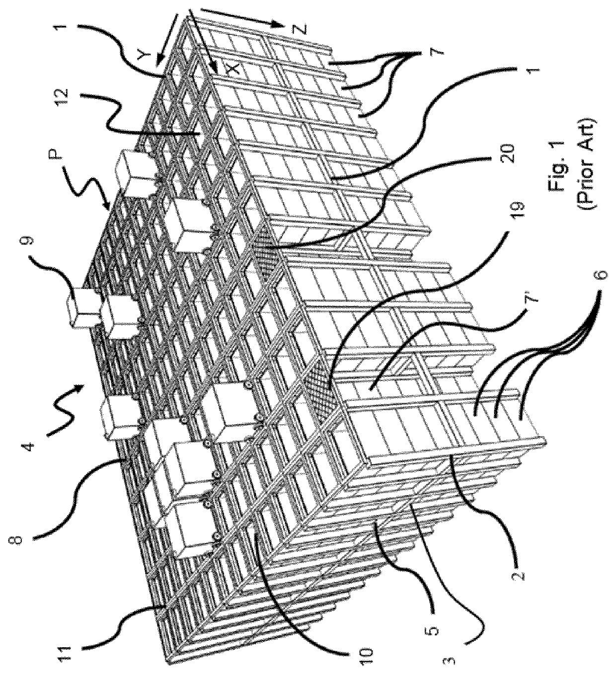
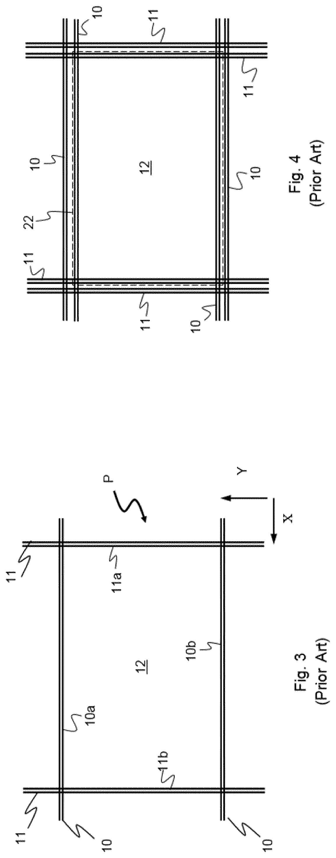
[0115]FIG. 3 is a top view of a grid 4 with a rail system 8 of the automated storage and retrieval system. The grid 4 comprises a framework structure 1 comprising a plurality of upright members 2 (see FIG. 1) and a plurality of horizontal members 3 which are supported by the upright members. As is known in the art, the upright and horizontal members may typically be made of metal,...


PUM


Abstract

An automated storage and retrieval system comprises a rail system comprising a first set of parallel tracks arranged in a horizontal plane and extending in a first direction, and a second set of parallel tracks arranged in the horizontal plane and extending in a second direction which is orthogonal to the first direction, which first and second sets of tracks form a grid pattern in the horizontal plane comprising a plurality of adjacent grid cells, each comprising a grid opening defined by a pair of neighboring tracks of the first set of tracks and a pair of neighboring tracks of the second set of tracks; and a plurality of stacks of storage containers arranged in storage columns located beneath the rail system. Each storage column is located vertically below a grid opening. A container handling vehicle comprises a transport mechanism for transport of the vehicle on the rail system, a lifting assembly for picking up storage containers from the storage columns to a position above the lowest level of the transport mechanism. The lifting assembly comprises a lifting frame connectable to a storage container, a first lifting shaft and a second lifting shaft, the first and second lifting shafts being mainly parallel, and each of the first and second lifting shafts being supported in an upper portion of the vehicle, two lifting elements extending from each of the first and second lifting shafts to the lifting frame, a motor drive assembly comprising at least a first motor, wherein the at least first motor encircles one of the lifting shafts, and a force transferring assembly rotatably connecting the first and second lifting shafts via a force transferring element.

Description

[0001]The present invention relates to an automated storage and retrieval system, a container handling vehicle which can operate on an automated storage and retrieval system, and a method of operating an automated storage and retrieval system.BACKGROUND AND PRIOR ART[0002]FIG. 1 discloses a framework structure 1 of a typical prior art automated storage and retrieval system and FIGS. 2A-2C disclose different container handling vehicles 9 of such a system.[0003]The framework structure 1 comprises a plurality of upright members 2 and a plurality of horizontal members 3, which are supported by the upright members 2. The members 2, 3 may typically be made of metal, e.g. extruded aluminium profiles.[0004]The framework structure 1 defines a storage grid 4 comprising storage columns 5 arranged in rows, in which storage columns 5 store storage containers 6, also known as bins, are stacked one on top of another to form stacks 7. Each storage container 6 may typically hold a plurality of produ...

Claims


Application Information

Patent Timeline
Patent Type & Authority Patents(United States)
IPC IPC(8): B65G1/04B65G1/06B65G1/137
CPCB65G1/0464B65G1/065B65G1/0492B65G1/1378B65G2201/0235G05D2201/0216B66C1/101B66B15/06B66B11/0075
Inventor FJELDHEIM, IVARBEKKEN, BØRGEAUSTRHEIM, TROND
Owner AUTOSTORE TECH AS
Why Eureka
Try Eureka