Apparatus and method for sensing ice thickness and detecting failure modes of an ice maker

a technology of failure mode and ice maker, which is applied in the field of automatic ice making machines, can solve the problems of large ice cubes that cannot be easily separated into smaller pieces or individual cubes, sensor is a moving part and could fail, and small cubes of ice that may not be harvested properly

Active Publication Date: 2014-07-31
TRUE MFG CO INC
View PDF4 Cites 42 Cited by
  • Summary
  • Abstract
  • Description
  • Claims
  • Application Information

AI Technical Summary

Benefits of technology

[0015]Briefly, therefore, one embodiment of the invention is directed to an ice maker, wherein the ice maker includes a refrigeration system comprising a compressor, a condenser, a thermal expansion valve, an evaporator assembly, a freeze plate thermally coupled to the evaporator assembly, and a hot gas valve. The ice maker further includes a water system comprising a water pump, a water distribution tube, a purge valve, a water inlet valve, and a sump located below the freeze plate adapted to hold water. The ice maker also includes a control system comprising an air fitting, a pneumatic tube and a controller. The air fitting is disposed in the sump and defines a chamber in which air may be trapped and the air fitting includes one or more openings through which water in the sump is in fluid communication with the air in the chamber. The pneumatic tube has a proximal end and a distal end, wherein the distal end is connected to and in fluid communication with the air fitting. The controller comprises a processor and an air pressure sensor. The proximal end of the pneumatic tube is connected to and in fluid communication with the air pressure sensor. The air pressure sensor is adapted to sense an air pressure from the water in the sump compressing the air in the chamber of the air fitting, wherein the sensed pressure corresponds to a water level in the sump. The controller is adapted to control the operation of the refrigeration system and the operation of the water system based upon the water level in the sump and to detect one or more failure modes of the water system based upon the water level in the sump.
[0016]Another embodiment of the invention is a method of controlling an ice maker wherein the ice maker includes a refrigeration system comprising a compressor, a condenser, a thermal expansion valve, an evaporator assembly, a freeze plate thermally coupled to the evaporator assembly, and a hot gas valve. The ice maker further includes a water system comprising a water pump, a water distribution tube, a purge valve, a water inlet valve, and a sump located below the freeze plate adapted to hold water. The ice maker also includes a control system comprising an air fitting, a pneumatic tube and a controller. The air fitting is disposed in the sump and defines a chamber in which air may be trapped and the air fitting includes one or more openings through which water in the sump is in fluid communication with the air in the chamber. The pneumatic tube has a proximal end and a distal end, wherein the distal end is connected to and in fluid communication with the air fitting. The controller comprises a processor and an air pressure sensor. The proximal end of the pneumatic tube is connected to and in fluid communication with the air pressure sensor. The air pressure sensor is adapted to sense an air pressure from the water in the sump compressing the air in the chamber of the air fitting, wherein the sensed pressure corresponds to a water level in the sump. The method of controlling the ice maker comprises measuring the water level in the sump during a sensible cooling cycle to determine if the water level is varying beyond an acceptable range and detecting a leak failure mode if the water level in sump varies beyond the acceptable range during the sensible cooling cycle.

Problems solved by technology

Harvesting too early yields small cubes of ice that may not harvest properly.
Harvesting too late yields large chunks of ice that do not easily separate into smaller pieces or individual cubes.
However, this approach has a number of drawbacks.
Thus, the sensor is a moving part which could fail by not moving correctly.
Thus the sensor must be in exactly the right position or it will not work as desired.
Additionally, the ice thickness cannot be adjusted electronically because the ice thickness is controlled by the position of the set screw or other mechanical means.
Consequently, the ice thickness can only be adjusted mechanically.
This method is subject to fouling of the sensor with minerals or other contaminants that would adhere to the sensor and prevent electrical conductivity necessary to signal ice thickness.
Therefore even with an acoustic sensor, the ice thickness can only be adjusted manually, not electronically.
Similar to acoustic sensors, capacitive sensors may also be used but suffer from similar drawbacks.
However, a shortcoming of the Billman et al. patents is that because Billman et al. do not measure ice thickness directly, Billman et al. can mistake water leaks in the system as the formation or non-formation of ice on the freeze pla
stem. The systems and methods described by Billman et al. would be fooled by this leak, causing a harvest cycle to occur even though the ice cubes are not fully formed, resulting in undersized ice
If water is leaking from the water supply into the water system of the ice machine, oversized ice slabs will result because the controller of Billman et al. will incorrectly detect that the higher water level is the result of less freezing, not the result of additional water entering the system.
These oversized slabs may be difficult to separate into small pieces of ice or individual cubes.
In the case of a serious leakage of water from the water supply into the ice maker water system, the sensor of Billman et al. would continue to make ice long after the desired ice thickness has been reached and a major failure of the ice maker will result, which could include an uncontrolled water leakage into the ice machine's surroundings.
Four possible failure modes in an ice maker may include: (i) a failure of the water supply to the ice maker; ii) a failure of the ice maker's water inlet valve; iii) a failure of the ice maker's purge valve; and iv) a failure of the ice maker's water pump.
For example, a failure of the water supply can be caused by a water supply valve (e.g., a building or facility water supply valve external to the ice machine) being turned off or a failure of the water inlet valve in the ice maker to open.
This failure can result in the ice maker running out of water and no longer being able to manufacture ice.
A failure of the ice maker's water inlet valve can, if the water inlet valve fails CLOSED, prevent the ice maker from getting water, subsequently preventing the ice maker from making ice.
If the water inlet valve fails OPEN, too much water may be supplied to the ice maker, possibly causing a loss in ice making performance (because there is too much water to freeze) or a leak of water into the environment around the ice maker.
A failure of the ice maker's purge valve may result in an excess of water impurities collecting in the water in the sump and may cause the ice to be cloudy and / or the ice maker to stop functioning due to mineral accumulation.

Method used


Image

  • Apparatus and method for sensing ice thickness and detecting failure modes of an ice maker
  • Apparatus and method for sensing ice thickness and detecting failure modes of an ice maker
  • Apparatus and method for sensing ice thickness and detecting failure modes of an ice maker

Examples


Embodiment Construction

[0027]Before any embodiments of the invention are explained in detail, it is to be understood that the invention is not limited in its application to the details of construction and the arrangement of components set forth in the following description or illustrated in the following drawings. The invention is capable of other embodiments and of being practiced or of being carried out in various ways. Also, it is to be understood that the phraseology and terminology used herein is for the purpose of description and should not be regarded as limiting. The use of “including,”“comprising,” or “having” and variations thereof herein is meant to encompass the items listed thereafter and equivalents thereof as well as additional items.

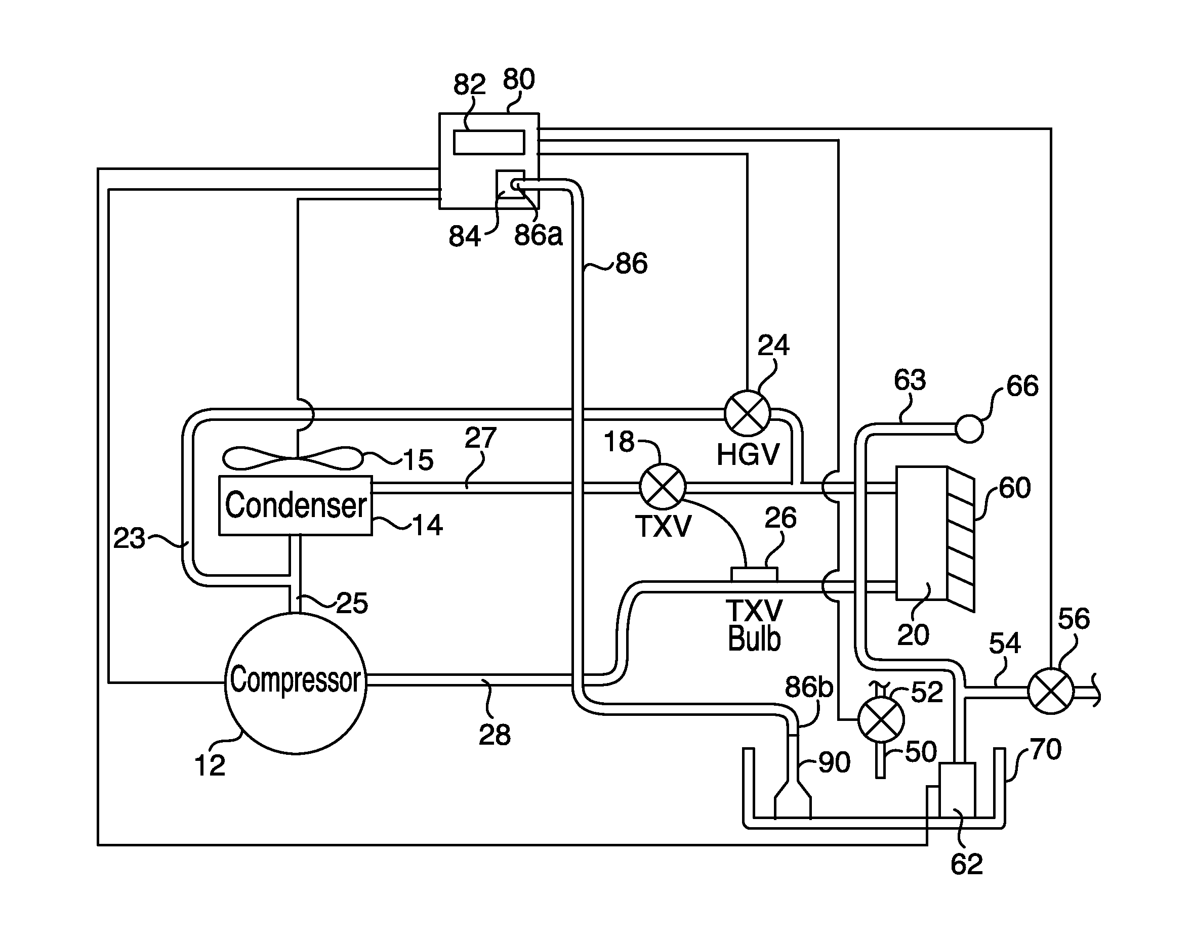
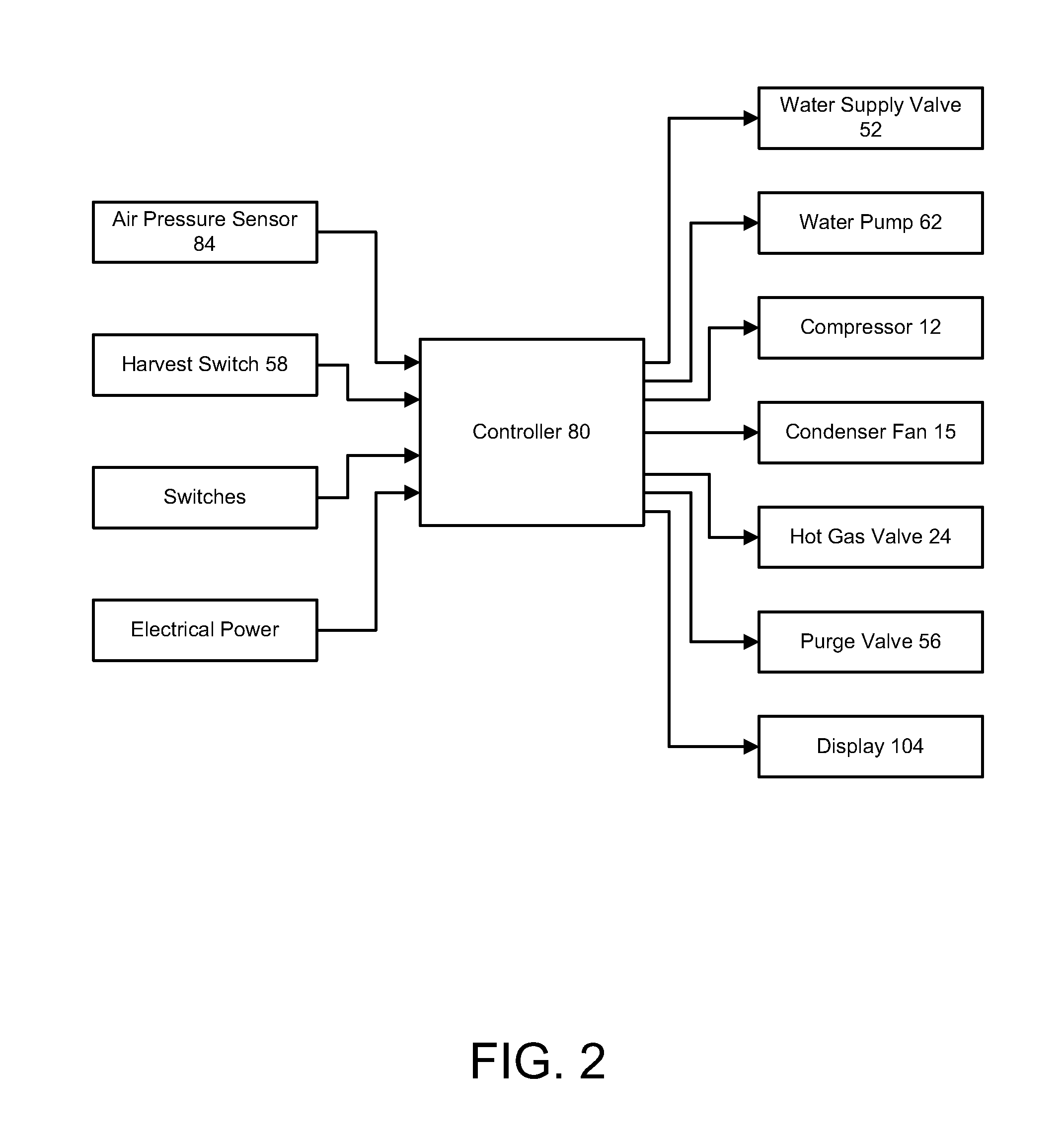
[0028]Embodiments of the ice maker described herein comprise a controller and an air pressure sensor which permit the detection of the thickness of the formation of ice on a freeze plate in an ice maker. Additionally, the controller and air pressure sensor allo...


PUM


Abstract

An ice maker comprising a refrigeration system, a water system, and a control system. The control system includes an air fitting disposed in the sump of the water system, a pneumatic tube, and a controller comprising a processor and an air pressure sensor. The air fitting defines a chamber in which air may be trapped and includes openings through which water in the sump is in fluid communication with the air in the chamber. The pneumatic tube is in fluid communication with the air pressure sensor and the air fitting. The air pressure sensor is adapted to sense a pressure corresponding to a sump water level. The controller is adapted to control the operation of the refrigeration system and the operation of the water system based upon the sump water level and to detect one or more failure modes of the water system based upon the sump water level.

Description

FIELD OF THE INVENTION[0001]This invention relates generally to automatic ice making machines and, more particularly, to ice making machines comprising systems and employing methods which permit for more reliably and controllably determining when to initiate a harvest cycle and for detecting the occurrence of a failure mode.BACKGROUND OF THE INVENTION[0002]Ice making machines, or ice makers, that employ freeze plates which comprise lattice-type cube molds and have gravity water flow and ice harvest are well known and in extensive use. Such machines have received wide acceptance and are particularly desirable for commercial installations such as restaurants, bars, motels and various beverage retailers having a high and continuous demand for fresh ice.[0003]In these ice makers, water is supplied at the top of a freeze plate which directs the water in a tortuous path toward a water pump. A portion of the supplied water collects on the freeze plate, freezes into ice and is identified as...

Claims


Application Information

Patent Timeline
Patent Type & Authority Applications(United States)
IPC IPC(8): F25C5/00
CPCF25C5/002F25C2400/14F25C2600/04F25C5/185F25C2700/04
Inventor BROADBENT, JOHN ALLEN
Owner TRUE MFG CO INC
Why Eureka
Try Eureka