

Artificial Photosynthetic System Using Photocatalyst
a photocatalyst and photocatalyst technology, applied in physical/chemical process catalysts, metal/metal-oxide/metal-hydroxide catalysts, instruments, etc., can solve the problems of low reaction rate of current photocatalytic systems, increasing the damage of burning fossil fuels, and increasing the damage of fossil fuels, so as to speed up the redox reaction and inhibit the recombination of electron holes. , the effect of speeding up th
Inactive Publication Date: 2014-07-31
SUNPOWER TECH CORP
View PDF6 Cites 7 Cited by
- Summary
- Abstract
- Description
- Claims
- Application Information
AI Technical Summary
Benefits of technology
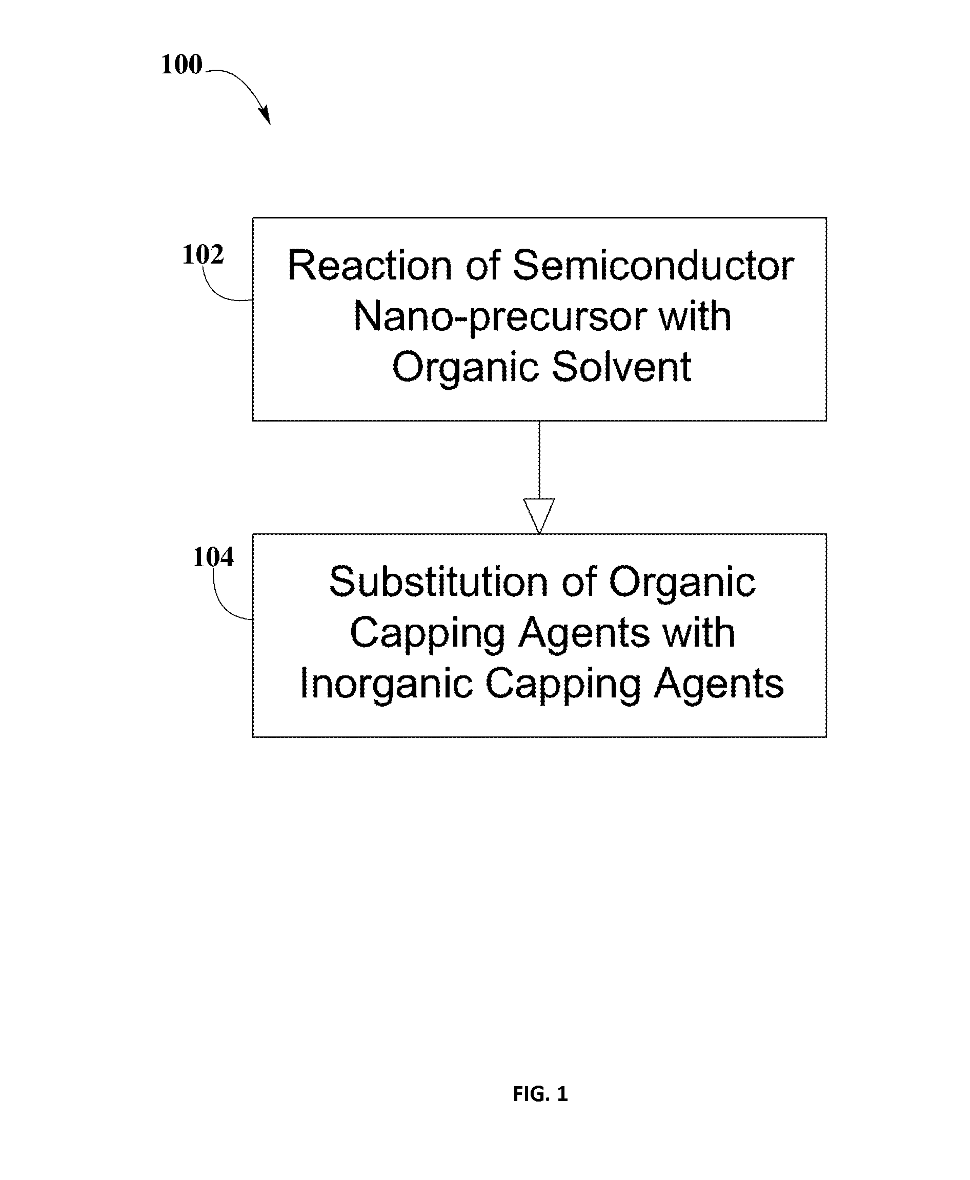
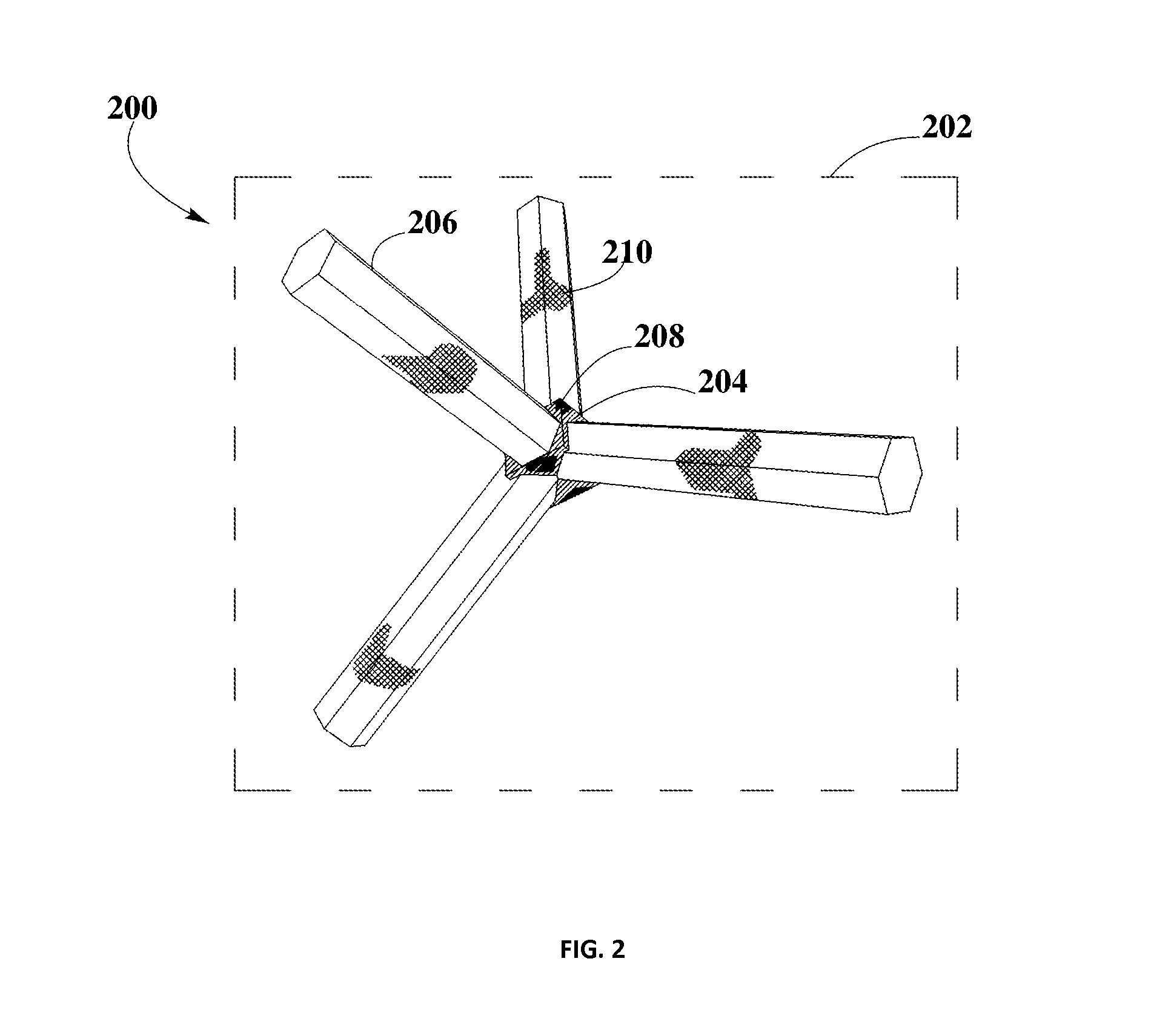
The inorganic capping agents in the photoactive materials help to speed up the redox reactions by quickly transferring the charge carriers from the semiconductor nanocrystals to water. This allows for faster and more efficient water splitting and CO2 reduction, while also inhibiting electron-hole recombination.
Problems solved by technology
The conversion of sunlight and water into a clean, high efficiency chemical fuel has been a goal for a number of years and the urgency increases as damaging effects of burning fossil fuels becomes ever more apparent.
In general, current photocatalytic systems suffer from low reaction rates.
Method used
View moreImage
Smart ImageViewing Examples

Examples
examples
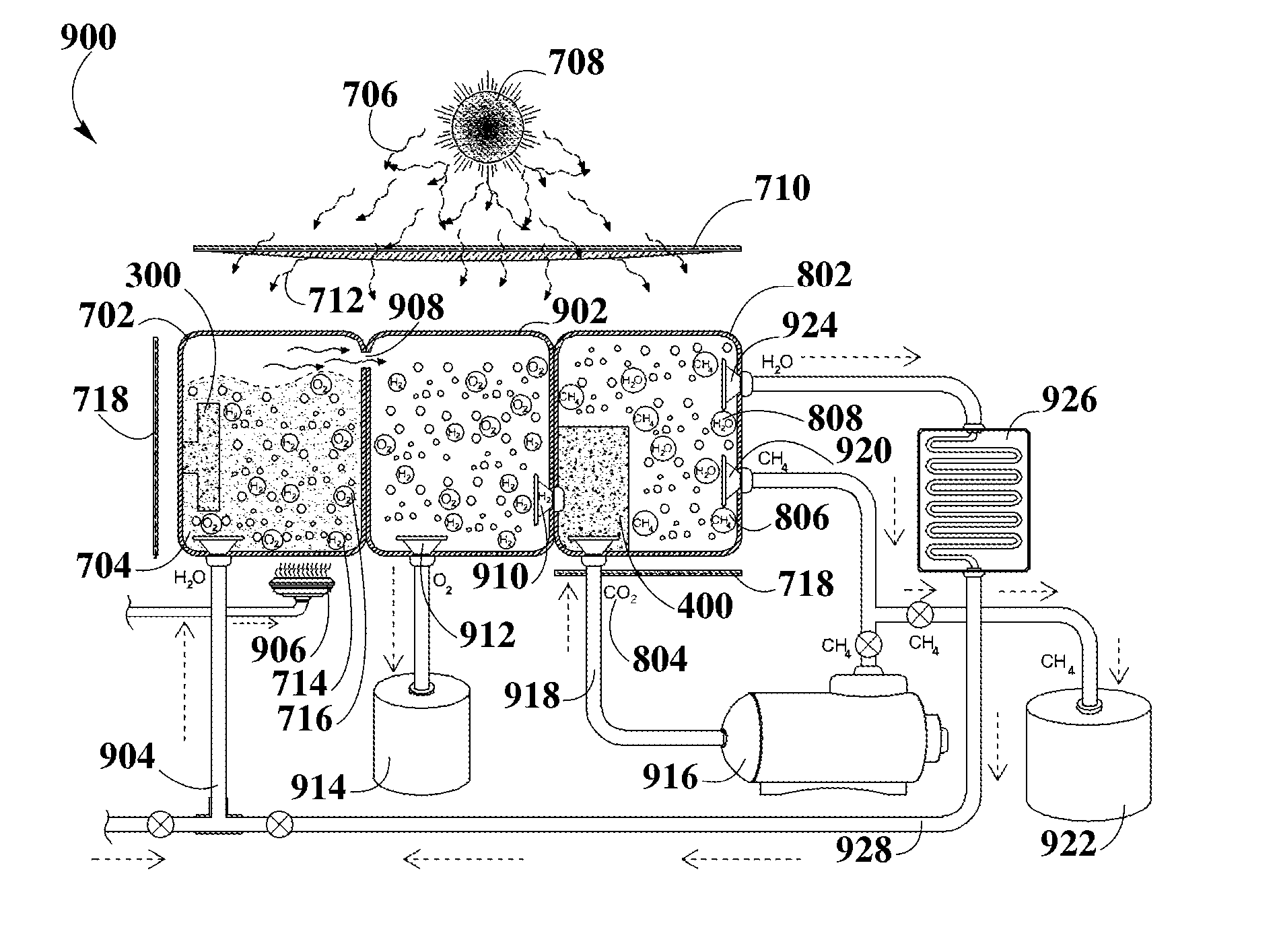
[0113]Example #1 is an embodiment of photosynthetic system 900 where gas collecting chamber 902 is not included, in which oxygen gas 716 and hydrogen gas 714 from reaction vessel A 702 may be transferred directly into reaction vessel B 802. Hydrogen gas 714 may pass through hydrogen permeable membrane 910 in order to be transferred into reaction vessel B 802; oxygen gas 716 may pass through oxygen permeable membrane 912 in order to be collected into an oxygen storage tank 914.
Login to View More PUM
| Property | Measurement | Unit |
|---|---|---|
| energy | aaaaa | aaaaa |
| band gap | aaaaa | aaaaa |
| band gap | aaaaa | aaaaa |
Abstract
A photosynthetic system for splitting water to produce hydrogen and using the produced hydrogen for the reduction of carbon dioxide into methane is disclosed. The disclosed photosynthetic system employs photoactive materials that include photocatalytic capped colloidal nanocrystals within their composition, in order to harvest sunlight and obtain the energy necessary for water splitting and subsequent carbon dioxide reduction processes. The photosynthetic system may also include elements necessary to transfer water produced in the carbon dioxide reduction process, for subsequent use in water splitting process. The systems may also include elements necessary to store oxygen and collect and transfer methane, for subsequent transformation of methane into energy.
Description
BACKGROUND[0001]1. Field of the Disclosure[0002]The present disclosure relates generally to artificial photosynthetic systems, in particular to a system that combines photocatalytic materials for hydrogen and methane production.[0003]2. Background Information[0004]The conversion of sunlight and water into a clean, high efficiency chemical fuel has been a goal for a number of years and the urgency increases as damaging effects of burning fossil fuels becomes ever more apparent. Fossil fuels are used in just about every sector of the modern industry and society, about 45% of the United States energy was produced by petroleum and coal in 2010, during this same year only 8% was recorded to be produced by renewable energy supplies. It is well known that it takes hundreds of millions of years for fossil fuels to be formed, and even more important, scientific studies have forecasted the end of fossil fuels by 2100.[0005]The conventional methods form described the formation of photocatalyti...
Claims
Login to View More Application Information
Patent Timeline
 Patent Type & AuthorityApplications(United States)
IPC IPC(8): B01J35/02C25B1/00C25B3/25
CPCC25B1/003B01J35/02B01J37/0215B01J27/0573B01J27/04B01J23/06C07C1/12C07C2527/057C07C2523/66C07C2523/06C07C2523/14C07C2527/04C10L3/08B01J35/58B01J35/23C07C9/04C25B1/55B01J35/00B01J35/30B01J35/40
InventorLANDRY, DANIEL
OwnerSUNPOWER TECH CORP