Photo-catalytic Systems for Production of Hydrogen

a photocatalytic and photocatalytic technology, applied in the field of photocatalytic systems, can solve the problems of limited success and limit the practical application of such systems, and achieve the effects of reducing the probability of electron and hole recombining, accelerating redox reactions, and increasing electron production

Inactive Publication Date: 2014-11-20
SUNPOWER TECH CORP
View PDF0 Cites 26 Cited by
  • Summary
  • Abstract
  • Description
  • Claims
  • Application Information

AI Technical Summary

Benefits of technology

[0011]A method for producing PCCN may include semiconductor nanocrystals synthesis and substituting organic capping agents with inorganic capping agents. The morphologies of semiconductor nanocrystals may include nanocrystals, nanorods, nanoplates, nanowires, dumbbell-like nanoparticles, and dendritic nanomaterials, among others. Each morphology may include an additional variety of shapes such as spheres, cubes, tetrahedra (tetrapods), among others. Varying sizes and shapes of PCCN may assist in tuning band gaps for absorbing different wavelengths of light.
[0015]The structure of PCCN may speed up redox reactions by quickly transferring charge carriers sent by plasmonic nanoparticles to water. In addition, there may be a higher production of electrons and holes being used in redox reactions, since PCCN within the photoactive material may be designed to separate holes and electrons immediately upon the accelerated formation by plasmonic nanoparticles triggered by LSPR, thus reducing the probability of electrons and holes recombining. Consequently, the redox reaction and water splitting process may occur at a faster and more efficient rate. Additionally, high surface area of PCCN may enhance efficiency of light absorption and of charge carrier dynamics.

Problems solved by technology
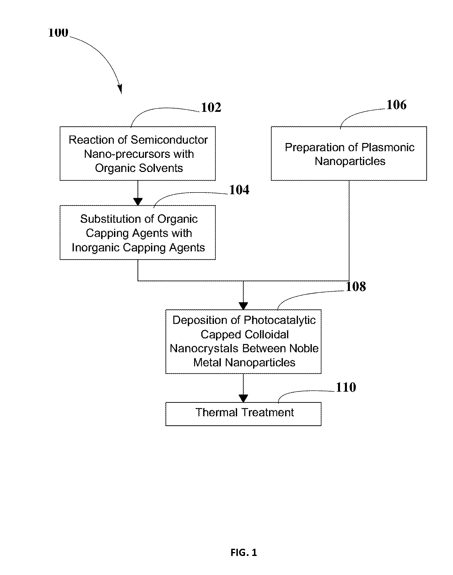
These attempts, however, have met with limited success.
However, corrosion or dissolution of noble metal particles in the course of a photocatalytic reaction is very likely to limit the practical application of such systems.

Method used


Image

  • Photo-catalytic Systems for Production of Hydrogen
  • Photo-catalytic Systems for Production of Hydrogen
  • Photo-catalytic Systems for Production of Hydrogen

Examples


examples

[0114]Example #1 is an embodiment of PCCN 302 in spherical shape 1000, as shown in FIG. 10, which may include a single semiconductor nanocrystal 1002 capped with a first inorganic capping agent 1004 and a second inorganic capping agent 1006.

[0115]In an embodiment, single semiconductor nanocrystal 1002 may be PbS quantum dots, with SnTe44− used as first inorganic capping agent 1004 and AsS33− used as second inorganic capping agent 1006, therefore forming a PCCN 302 represented as PbS.(SnTe4;AsS3).

[0116]The shape of semiconductor nanocrystals 1002 may improve photocatalytic activity of semiconductor nanocrystals 1002. Changes in shape may expose different facets as reaction sites and may change the number and geometry of step edges where reactions may preferentially take place.

[0117]Example #2 is an embodiment of PCCN 302 in nanorod shape 1100, as shown in FIG. 11. According to an embodiment, there may be three CdSe regions and four CdS regions as first semiconductor nanocrystal 1102 ...


PUM

PropertyMeasurementUnit
band gapaaaaaaaaaa
diameteraaaaaaaaaa
diameteraaaaaaaaaa

Abstract

A system for splitting water and producing hydrogen for later use as an energy source may include the use of a photoactive material including PCCN and plasmonic nanoparticles. A method for producing the PCCN may include a semiconductor nanocrystal synthesis and an exchange of organic capping agents with inorganic capping agents. The PCCN may be deposited between the plasmonic nanoparticles and may act as photocatalysts for redox reactions. The photoactive material may be used in presence of water and sunlight to split water into hydrogen and oxygen. Production of charge carriers may be triggered by photo-excitation and enhanced by the rapid electron resonance from localized surface plasmon resonance of plasmonic nanoparticles. By combining different semiconductor materials for PCCN and plasmonic nanoparticles and by changing their shapes and sizes, band gaps may be tuned to expand the range of wavelengths of sunlight usable by the photoactive material. The system may include elements for collecting, transferring, and storing hydrogen and oxygen, for subsequent transformation into electrical energy.

Description

CROSS-REFERENCE TO RELATED APPLICATIONS[0001]The disclosure here described is related to U.S. patent Ser. No. 13 / 722,355, filed Dec. 20, 2012, entitled “Photo-catalytic Systems for Production of Hydrogen,” and U.S. patent application Ser. No. 13 / 837,412, filed Mar. 15, 2013, entitled “Method for Increasing Efficiency of Semiconductor Photocatalysts,” all of which are incorporated herein by reference in their entirety.BACKGROUND[0002]1. Field of the Disclosure[0003]The present disclosure relates generally to photocatalysis, and more specifically to a hydrogen generation system in which solar energy is used for the photocatalytic decomposition of water and production of hydrogen employing plasmonic nanoparticles and photocatalysts.[0004]2. Background Information[0005]Photoactive materials used for water splitting require a strong UV / visible light absorption, high chemical stability in the dark and under illumination, suitable band edge alignment to enable redox reactions, efficient ch...

Claims


Application Information

Patent Timeline
Patent Type & Authority Applications(United States)
IPC IPC(8): C01B3/04
CPCB82Y99/00C01B3/042B82Y30/00B82Y40/00C01B3/501C01B13/0207C01B13/0251Y02E60/36
Inventor JENNINGS, TRAVISLANDRY, DANIEL
Owner SUNPOWER TECH CORP
Why Eureka
Try Eureka