
Power line carrier communication reception circuit

a technology of communication reception and power line carrier, applied in pulse manipulation, pulse automatic control, pulse technique, etc., can solve the problems of distorted transmission signal, increased manufacturing cost, and increased manufacturing cost, so as to reduce manufacturing cost, minimize external noise, and operate stable

Inactive Publication Date: 2014-07-31
RIB LAB +1
View PDF2 Cites 5 Cited by
  • Summary
  • Abstract
  • Description
  • Claims
  • Application Information

AI Technical Summary

Benefits of technology

The patent text discusses a problem with traditional carrier band transmission methods which require processing signals for each frequency band. This leads to increased manufacturing costs due to the need for multiple elements and high-speed operations. The technical effect of the patent is to provide a solution to simplify the processing of signals for carrier band transmission, reducing manufacturing costs.

Problems solved by technology

However, it is necessary to process signals whose number corresponds to the number of frequency bands of carrier waves to be used since a plurality of carrier waves is used for the above carrier band transmission, and therefore there is a problem that multiple elements are required and thereby increase manufacturing cost.
In addition, frequencies of carrier waves are set sufficiently high compared to a bit rate of data to be communicated, and therefore there is also a problem that elements which operate at a high speed are required, and thereby increase manufacturing cost.
On the other hand, when baseband transmission is performed, a transmission signal is superimposed on a power line which feeds power, and therefore since transmission efficiency of a signal is poor compared to communication which uses a normal communication line and, above all, since an impedance of a power line is low, there is a problem that the transmission signal is distorted as if the transmission signal were subjected to a differential operation.
Further, when a level of a signal to be transmitted is too high, this signal is likely to leak to a surrounding as an electromagnetic wave, and therefore, an input level of a signal to be received using a power line cannot help weakening, thereby making reception of the signal difficult.
In addition, when the reception circuit is used in a system in which a battery of a limited size is used to arrange the reception circuit in limited space as in a vehicle, there is a problem that an error occurs upon quantization of a received signal due to a significant fluctuation of a power voltage in a power supply line following driving of a load.
That is, when whether or not the received signal is high or low is determined based on whether or not the received signal exceeds a predetermined reference threshold, a fluctuation of a power voltage significantly influences the received signal and causes an error of the received signal.

Method used


Image

  • Power line carrier communication reception circuit
  • Power line carrier communication reception circuit
  • Power line carrier communication reception circuit

Examples


Embodiment Construction

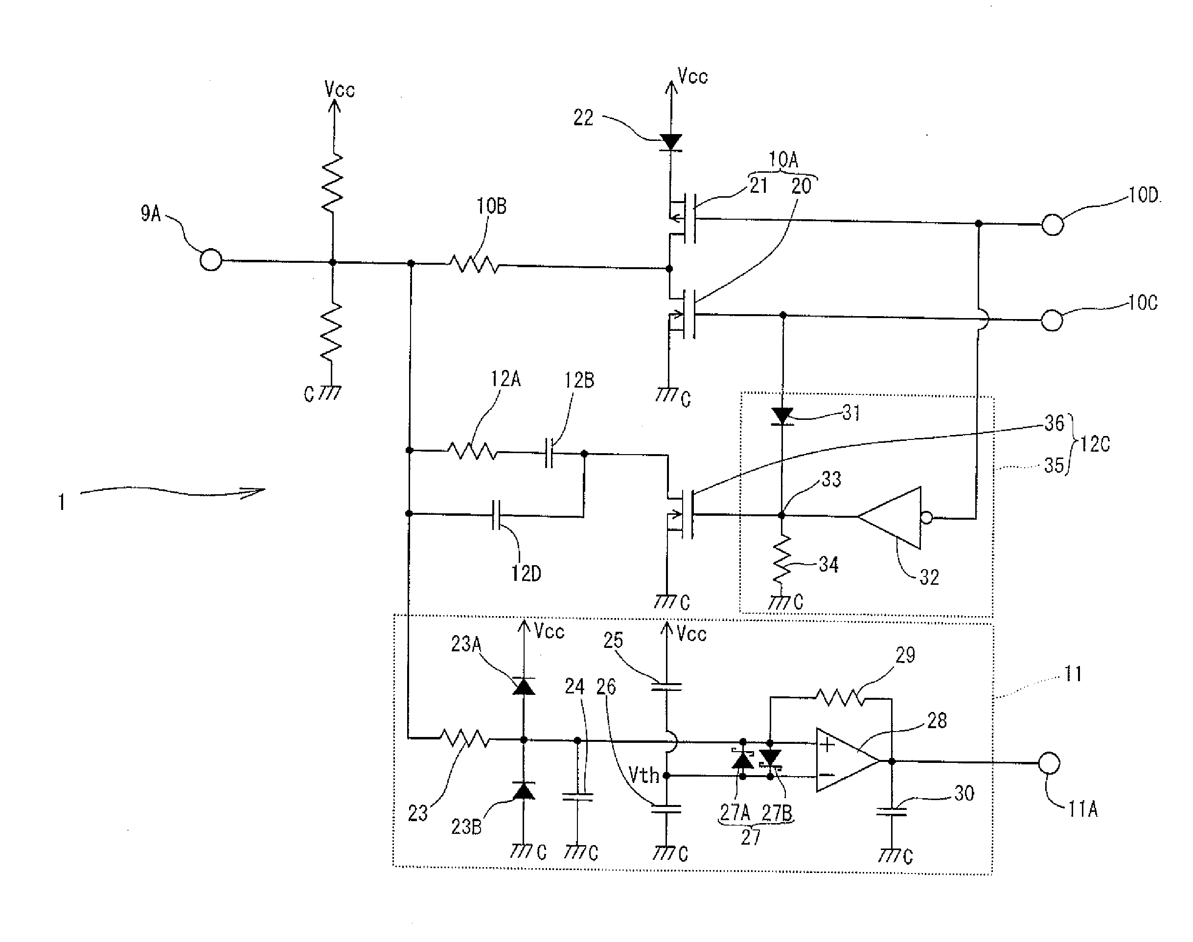
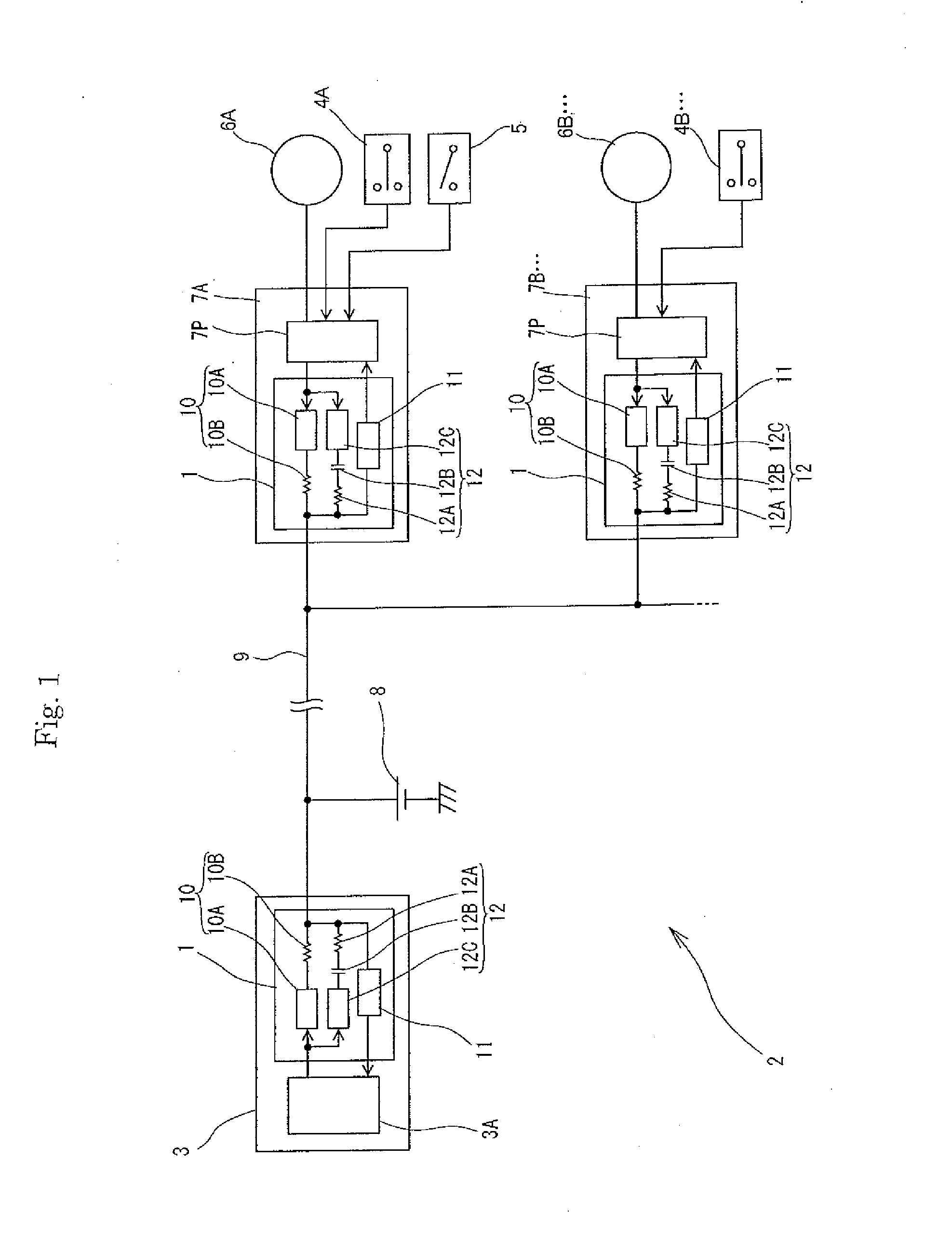
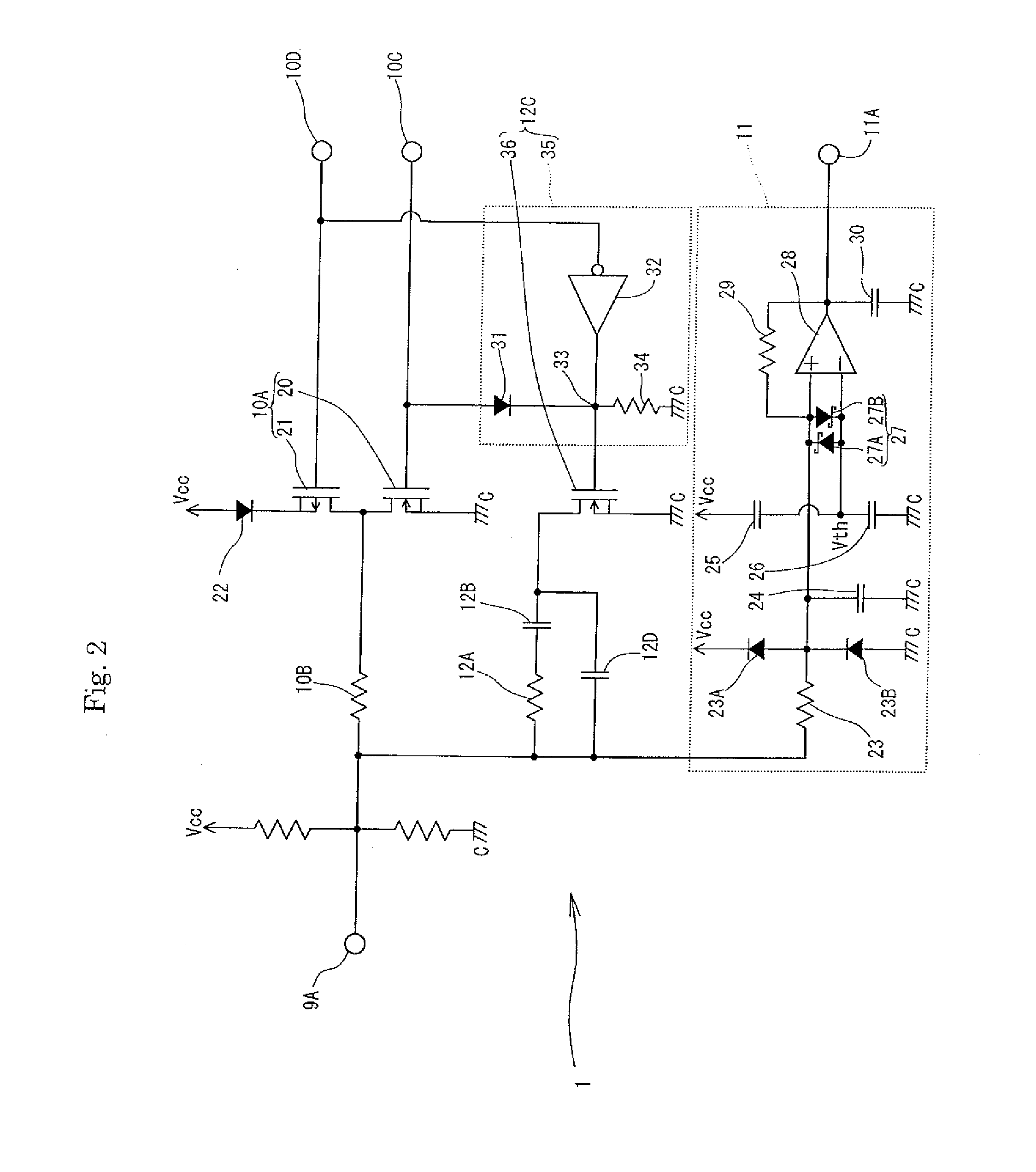
[0026]A power line carrier communication reception circuit 11 according to a first embodiment of the present invention will be described below using FIGS. 1 and 2. As illustrated in FIG. 1, the power line carrier communication reception circuit 11 according to the present invention is used as a main unit of a communication system 2 of a vehicle.

[0027]The communication system 2 illustrated in FIG. 1 has: an electronic control unit (ECU) 3 which performs communication with, for example, each electrical device provided at each door of the vehicle; power window switches 4A, 4B . . . which are provided at the doors of the vehicle and operate windows to open and close; a window lock switch 5 which is provided at a door on a driver's seat side and forbids an operation of opening and closing the windows other than a window of the driver's seat; motors 6A, 6B . . . which are driving sources of power to open and close the windows; a contact point information collecting apparatus 7A which is c...


PUM


Abstract

A power line carrier communication reception circuit which can precisely receive a signal to be superimposed at such a signal level that leakage of an electromagnetic wave does not cause a problem while employing a simplified configuration is provided.The power line carrier communication reception circuit may include an amplifier which is connected to a power line and amplifies a received signal to be superimposed on the power line; two capacitors which are connected in series between both power sources of the amplifier; and a clipper circuit which connects connection points of these capacitors to the power line and limits the received signal in a predetermined range of a reference voltage between the capacitors, and in which the amplifier compares the signal limited by the clipper circuit and the reference voltage and amplifies the signal.

Description

BACKGROUND OF THE INVENTION[0001]1. Field of the Invention[0002]The present invention relates to a power line carrier communication reception circuit.[0003]2. Description of the Related Art[0004]Conventionally, power line carrier communication which uses a power line as a communication line is performed. A power line carrier communication apparatus is an apparatus which performs such communication using a power line, and can perform data communication between each power line carrier communication reception circuit connected by the power line.[0005]While there are various schemes of power line carrier communication, there are roughly carrier band transmission for modulating data to be communicated using a carrier wave of several Hz to several tens of MHz as a carrier, and baseband transmission which does not use a carrier wave. The carrier baseband transmission can not only perform communication which is hardly influenced by noise in the surrounding by selecting a frequency of a carr...

Claims


Application Information

Patent Timeline
Patent Type & Authority Applications(United States)
IPC IPC(8): H03K5/08
CPCH03K5/08
Inventor MORI, SETSUROTERADA, SHOHEIKONO, MOTOKI
Owner RIB LAB
Learn More