
Non-destructive inspection apparatus and method for toughened composite materials

a composite material and inspection apparatus technology, applied in the field of inspection apparatus and methods, can solve the problems of destructive optical evaluation of conventional inspection of toughened composite materials, complex variation of mechanical stresses of aircraft, and more strict requirements of composite materials

Inactive Publication Date: 2014-07-31
NAT TAIWAN UNIV
View PDF3 Cites 10 Cited by
  • Summary
  • Abstract
  • Description
  • Claims
  • Application Information

AI Technical Summary

Benefits of technology

The patent is about a new inspection apparatus that can inspect composite materials without damaging them. This means that it can be used on production lines without interrupting the process. The apparatus can also provide information about the distribution of fibers or toughened particles on the surface of the material.

Problems solved by technology

However, the aircraft sustains a complex variation of the mechanical stresses during takeoff and landing.
Moreover, the high altitude operation environment of the aircraft results in more strict requirements of composite materials.
The conventional inspection of the toughened composite materials is a destructive optical evaluation.
However, the cross-section represents only a small portion of the composite material and the distribution of toughened particles cannot be properly evaluated.
In other words, the conventional optical inspection fails to provide accurate information regarding the distribution of toughened particles such that the GIC and CAI cannot be properly predicted.
The abovementioned methods require considerable time and high cost.
Additionally, the information is not immediately provided to the production line and may result in defected products.

Method used


Image

  • Non-destructive inspection apparatus and method for toughened composite materials
  • Non-destructive inspection apparatus and method for toughened composite materials
  • Non-destructive inspection apparatus and method for toughened composite materials

Examples


Embodiment Construction

[0022]The aforementioned illustrations and following detailed descriptions are exemplary for the purpose of further explaining the scope of the instant disclosure. Other objectives and advantages related to the instant disclosure will be illustrated in the subsequent descriptions and appended drawings.

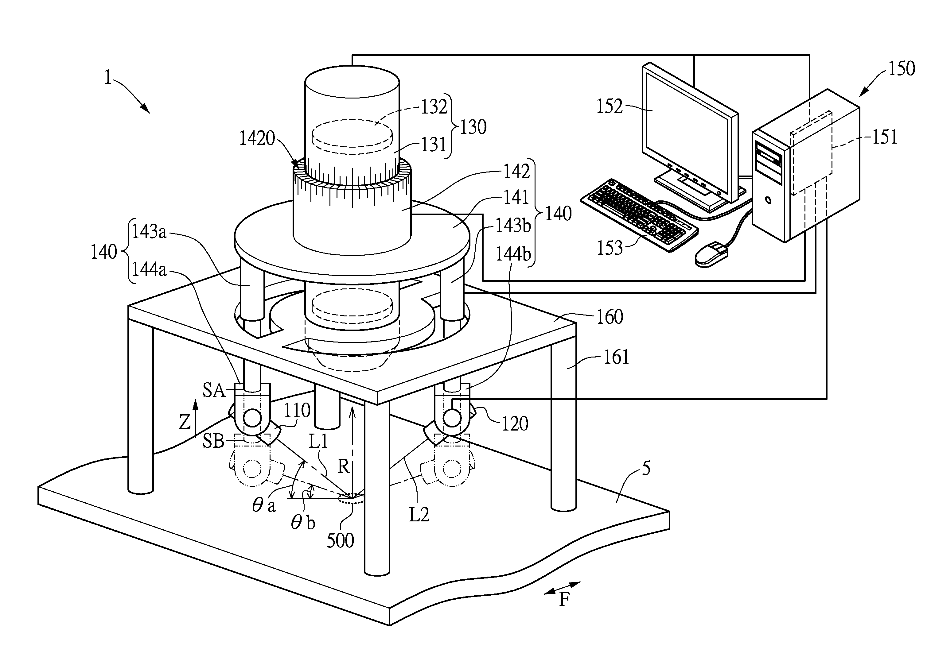
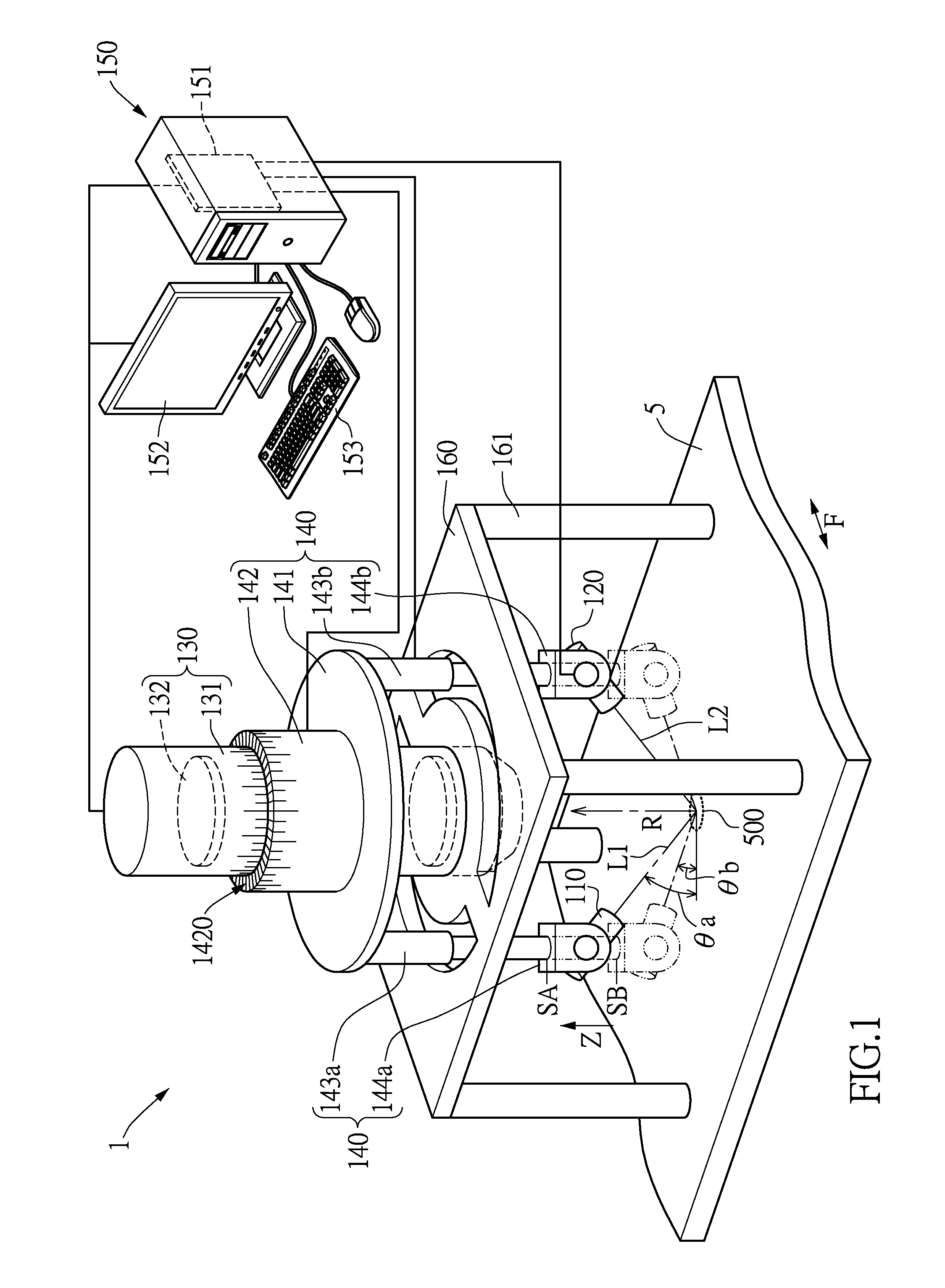
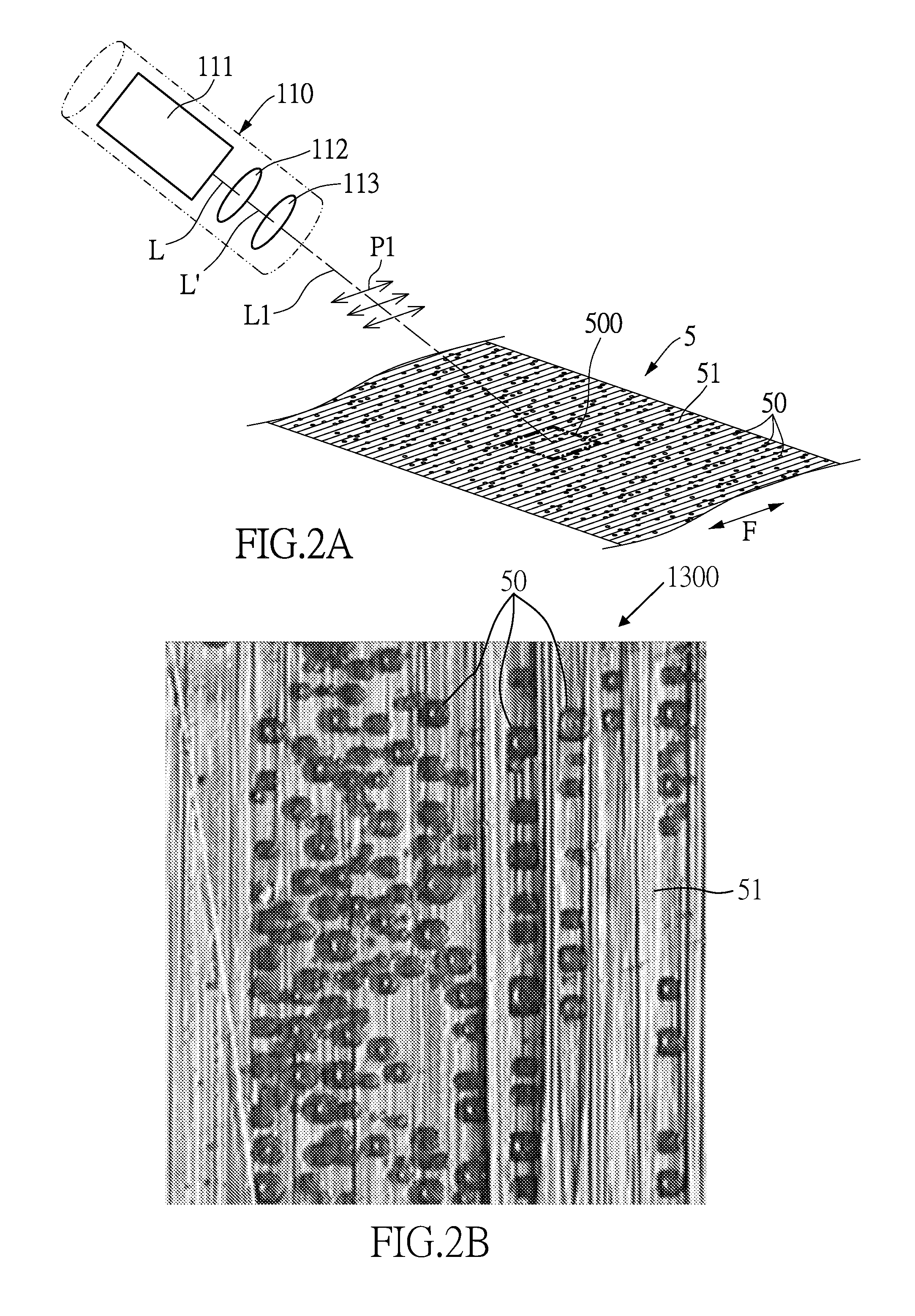
[0023]Please refer to FIG. 1 which shows a non-destructive composite material inspection apparatus in accordance with an embodiment of the instant disclosure. The composite material inspection apparatus 1 is suitable to evaluate the composite material 5. The composite material 5 is constituted by fibers and matrix enclosed therein. The composite material 5 can be stacked composite material, continuous fiber composite material, granular composite material or short fiber composite material. In the instant embodiment, the composite material 5 can be stacked or single-layered composite material or prepreg. The fibers of the surface layer of the composite material 5 have a fiber direction F...


PUM


Abstract

A non-destructive composite material inspection apparatus and method thereof inspect the fiber direction and fracture toughness. The apparatus includes a light module and a stereoscopic microcamera module. The light module generates a polarized light that has a polarization orientation projecting to an inspection area on the surface layer of the composite material. The stereoscopic microcamera module captures the reflection light from the inspection area and outputs an image. When the polarization orientation and the fiber direction are parallel, the image is a bright field image. When the polarization orientation and the fiber direction are orthogonal, the image is a dark field image. The bright and dark field images show the fiber direction and toughened particle distribution and the toughness of the composite material is then predicted.

Description

BACKGROUND[0001]1. Field of the Invention[0002]The instant disclosure relates to an inspection apparatus and method; in particular, to a non-destructive inspection apparatus and method for the fracture toughness and fiber direction of composite materials.[0003]2. Description of Related Art[0004]Composite materials, which include matrix and reinforcement materials, have been known in the art. Reinforcement materials such as carbon fiber or glass fiber enhance the strength and resistance of the final product. The matrix shapes the product and protects the reinforcement materials from wearing out by mechanical contacts.[0005]The composite materials with the reinforcement materials commonly exhibit light weight, high strength and high resistance to extreme weather conditions, corrosion and fatigue. Hence, composite materials with the reinforcement materials are widely implemented in various fields.[0006]Because of the rising price of oil, composite materials have been implemented in air...

Claims


Application Information

Patent Timeline
Patent Type & Authority Applications(United States)
IPC IPC(8): G06T7/00H04N13/02
CPCH04N13/0203G06T7/0004G01N2021/217G01N2021/8848G01N2021/8472G01N2021/8825H04N13/254H04N13/214G01N21/21G01N21/8806G01N2021/8822
Inventor HSIAO, HAO MING
Owner NAT TAIWAN UNIV
Learn More