
Noise Mitigating Microphone System

a microphone and noise-mitigating technology, applied in the field of microphones, can solve the problems of significant noise and hearing aids, and achieve the effect of mitigating electromagnetic interferen

Active Publication Date: 2014-07-31
INVENSENSE +1
View PDF16 Cites 11 Cited by
  • Summary
  • Abstract
  • Description
  • Claims
  • Application Information

AI Technical Summary

Benefits of technology

The patent describes a package for microphones that has a top, bottom, and sides that form an interior chamber. The package has two microphone dies that are stacked together with a circuit die. The circuit die uses a signal from one of the microphone dies to reduce noise. The microphone dies are positioned so that their diaphragms are symmetrically positioned relative to the inlet aperture. The package also has a lid and base that are made of plastic and conductive material to reduce electromagnetic interference. The technical effect of this design is an improved microphone system that reduces noise and improves signal quality.

Problems solved by technology

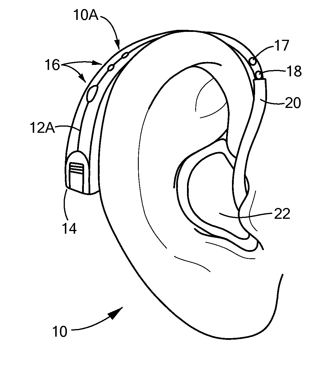
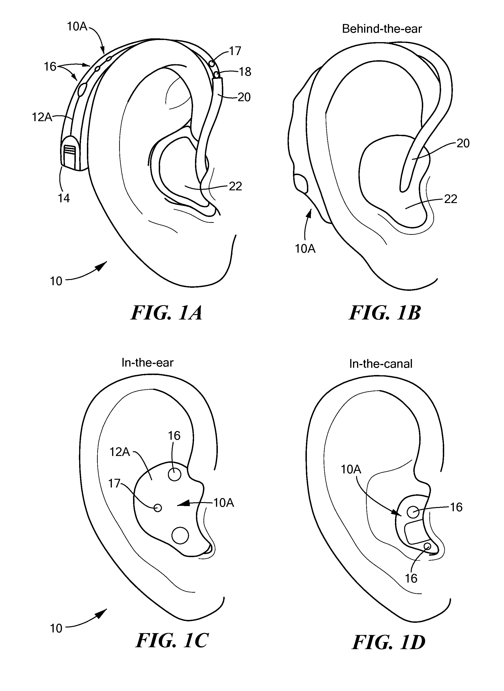
Moreover, certain devices undesirably cause a significant amount of noise.
For example, hearing aids can cause noise simply due to the normal movement of a user.

Method used


Image

  • Noise Mitigating Microphone System
  • Noise Mitigating Microphone System
  • Noise Mitigating Microphone System

Examples


Embodiment Construction

[0005]In accordance with one embodiment of the invention, a microphone system has a package forming an interior chamber and an inlet aperture for communicating the inlet chamber with the exterior environment (i.e., the environment outside of the interior chamber). The system also has first and second MEMS microphones in a stacked relationship within the interior chamber. The first MEMS microphone has a first movable diaphragm and a first backplate that together form a first variable capacitor. Likewise, the second MEMS microphone has a second movable diaphragm and a second backplate that together form a second variable capacitor. Both the first and second MEMS microphones are in fluid communication with the inlet aperture. The first MEMS microphone is configured to produce a first signal in response to receipt of an incoming acoustic signal striking the first diaphragm, and, in a similar manner, the second MEMS microphone is configured to produce a second signal in response to recei...


PUM


Abstract

A microphone system has a package with a top, a bottom, and four sides that at least in part form an interior chamber. One of the sides forms an inlet aperture for communicating the inlet chamber with the exterior environment. The system also has first and second microphone dies, in a stacked relationship, respectively having a first and second diaphragms. A circuit die, positioned in electrical communication with the first and second microphone dies, is configured to mitigate vibrational noise from the first microphone die using a signal produced by the second microphone die or vice versa. The first and second microphone dies are positioned so that the first and second diaphragms are substantially the same distance from the inlet aperture in the side.

Description

FIELD OF THE INVENTION[0001]The invention generally relates to microphones and, more particularly, the invention relates to packages for microphones.BACKGROUND OF THE INVENTION[0002]MEMS microphones are used in a growing number of devices, such as mobile telephones, laptop computers, voice recorders, hearing instruments, and other electronic devices. To those ends, MEMS microphone dies typically are mounted within a package interior and controlled by an adjacent integrated circuit die. For example, a MEMS microphone package may include a substrate, such as an FR-4 based printed circuit board (PCB), a MEMS microphone die attached to the substrate, and a cup-shaped lid attached to the substrate to create a package. The interior of the package forms an interior chamber that protects the fragile MEMS microphone die from the environment.[0003]The interior chamber is not completely isolated, however, from the external environment. Specifically, the package also has an aperture to permit c...

Claims


Application Information

Patent Timeline
IPC IPC(8): H04R3/00
CPCH04R3/002H04R19/04H04R1/04H04R1/10H04R3/005H04R5/027H04R19/005H04R25/00H04R2201/003H04R2410/05
Inventor BOLOGNIA, DAVIDMOSS, BRIAN
Owner INVENSENSE
Learn More