Multi-Material-Blade for Active Regenerative Magneto-Caloric and Electro-Caloric Heat Engines

a multi-material blade and active regenerative technology, applied in the direction of machines using electric/magnetic effects, sustainable buildings, operation modes, etc., can solve the problems of low frequency, low operating speed, heavy and expensive solution per watt of cooling, etc., and achieve the effect of reducing the loss in the system

Active Publication Date: 2014-08-07
CAMFRIDGE
View PDF6 Cites 66 Cited by
  • Summary
  • Abstract
  • Description
  • Claims
  • Application Information

AI Technical Summary

Benefits of technology

[0101]The method achieves to manufacture a Multi-Material-Blade that can be used as an AMR in an active regenerative magneto-caloric engine, and is particularly improved in terms of reducing the HE loss in the system.
[0102]The present invention is further directed to a method for fabricating a Multi-Material-Blade for use in an active regenerative magneto-caloric or electro-caloric engine. The method comprises the steps of forming a blade body from a plurality elements made from different magneto-caloric or electro-caloric materials, wherein the plurality of elements are arranged along the length of the blade body. The method further comprises the steps of forming a plurality of dedicated channels, which penetrate the blade body and extend along the length of the blade body, wherein each of

Problems solved by technology

The primary disadvantage is its low operating speed, typically only 0.1 Hz to 1 Hz.
The low frequency translates into a relatively large, heavy and expensive solution per Watt of cooling.
The frequency limitation arises due to high pressure drops across the porous packed bed AMR, when using a liquid exchange fluid, at higher frequencies.
The pressure drops results in large viscous and thus pumping losses.
Although utilizing a gaseous exchange medium could reduce the pressure drops and the viscous losses, the available cooling power is limited due to

Method used


Image

  • Multi-Material-Blade for Active Regenerative Magneto-Caloric and Electro-Caloric Heat Engines
  • Multi-Material-Blade for Active Regenerative Magneto-Caloric and Electro-Caloric Heat Engines
  • Multi-Material-Blade for Active Regenerative Magneto-Caloric and Electro-Caloric Heat Engines

Examples


second embodiment

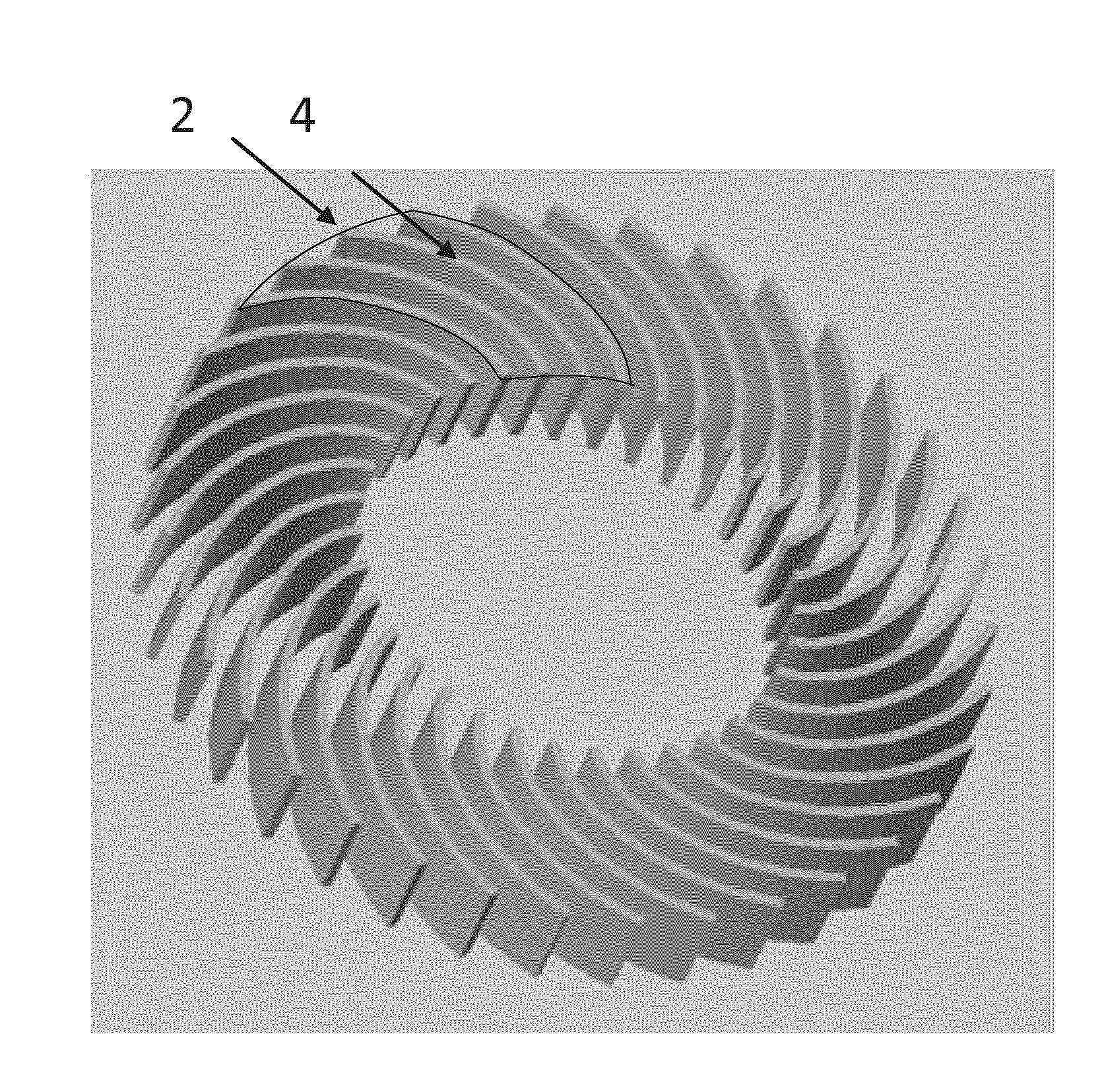
[0140]FIG. 7 shows one of a plurality of elements 2 of another second example of the present invention. The example is similar to and compatible with the first example, since again plates 4 can be stacked to form the plurality of elements 2. The blade body 1 of the second embodiment exhibits a cross-section that has regions of different porosity in one direction, which is in FIG. 7 the vertical direction. The regions of different porosity are separated from each other and defined by a sudden jump in porosity that is at least 10%, but is preferably at least 20%, more preferably at least 30%. In FIG. 7 plates 4 that represent regions of low porosity (the porosity can even be zero, but can also be of finite value) are alternatingly stacked on top of each other with porous layers 19 in between. The porous layers 19 form the dedicated channels 3 as well as the spacers 5. Exchange fluid will preferably flow through the region with the higher porosity (open structure), in the case of FIG. ...

first embodiment

[0156]FIG. 17 shows an example of how a Multi-Material-Blade according to the present invention, in particular the first embodiment, can be fabricated. In general a blade body 1 is formed of a plurality of elements 2, wherein each of the plurality of elements 2 is made from a different magneto-caloric or electro-caloric material. The plurality of elements 2 are arranged along the length of the blade body 1, and dedicated channels 3 are created that penetrate the blade body 1. Finally a mixing structure and / or a hydrophobic coating layer can be provided to each of the dedicated channels 3.

[0157]In FIG. 17 each of the plurality of elements 2 is formed by stacking a plurality of plates 4 on top of each other. Each of the plurality of plates 4 is formed by aligning sub-plates 16 in a frame 17, applying strips and dots 18 on the sub-plates and baking the aligned sub-plates 16 together with the frame 17, in order to form plates 4. Then the plates 4 are stacked on top of each other with sp...


PUM


Abstract

The present invention describes the design and fabrication of Multi-Material-Blades used as active regenerative regenerators in active regenerative magneto-caloric or electro-caloric engines. The blades consist of a plurality of elements (2) that divide the blade body along its length. Each element (2) is made of a different magneto-caloric or electro-caloric material selected appropriately, and a plurality of dedicated channels (3) penetrates the blade body (1) and extends along the length of the blade. The dedicated channels (3) can be provided with fluid mixing structures, porous layers or hydrophobic coatings to reduce the HE loss in an active regenerative engine. The Multi-Material-Blades are obtainable by ink jet printing techniques to reduce costs. The Multi-Material-Blades can further have a curved shape to form an involute blade body (1). All measures can improve the performance of active regenerative magneto-caloric or electro-caloric engines, and lay the basis for commercial solutions.

Description

INTRODUCTION[0001]The present invention relates to a Multi-Material-Blade for use in an active regenerative magneto-caloric or electro-caloric heat engine. In particular the Multi-Material-Blade acts as an active magnetic regenerator (AMR) or an active electro-caloric regenerator (AER) in the respective engine, and is designed to significantly improve its performance.[0002]Such heat engines are useable in cooling, heat pumping and energy recovery applications.[0003]The active magnetic regenerative engine and the active magnetic regenerator were first identified by Barclay (see e.g. U.S. Pat. No. 4,332,135) as being capable of exploiting the magneto-caloric effect of ferromagnetic materials, in order to deliver refrigeration and cooling over a relatively wide temperature range. An earlier device referred to as the Brown magneto-caloric device (see U.S. Pat. No. 4,069,028) also utilized a regenerative cycle, although not an active magnetic regenerative cycle.Materials[0004]Magneto-cal...

Claims


Application Information

Patent Timeline
IPC IPC(8): F25B21/00E04D13/08
CPCF25B21/00F25B2321/002Y02B30/00
Inventor OEZCAN, SIBELBURDETT, PAULWILSON, NEIL
Owner CAMFRIDGE
Why Eureka
Try Eureka