Miniature planar notch antenna using microstrip feed line

a microstrip and antenna technology, applied in the field of antennas, can solve the problems of significant increase in production cost and difficulty, and achieve the effect of reducing the dimension of the proposed antenna and increasing the effective length of the antenna

Inactive Publication Date: 2006-11-07
TAMKANG UNIVERSITY
View PDF3 Cites 3 Cited by
  • Summary
  • Abstract
  • Description
  • Claims
  • Application Information

AI Technical Summary

Benefits of technology

[0007]Another objective of the present invention is to provide a miniature antenna that could be achieved using low-cost manufacturing process on an ordinary substrate, instead of employing three-dimensional structure, mechanical drilling, or complicated processes such as LTCC.

Problems solved by technology

All these would lead to a significant increase of production cost and difficulty.

Method used


Image

  • Miniature planar notch antenna using microstrip feed line
  • Miniature planar notch antenna using microstrip feed line
  • Miniature planar notch antenna using microstrip feed line

Examples


Embodiment Construction

[0018]The present invention is based on a planar notch antenna excited by a microstrip feed line. A planar notch antenna using a microstrip feed line has been already known for its various advantages such as light weight, small size, simple production, and easy integration.

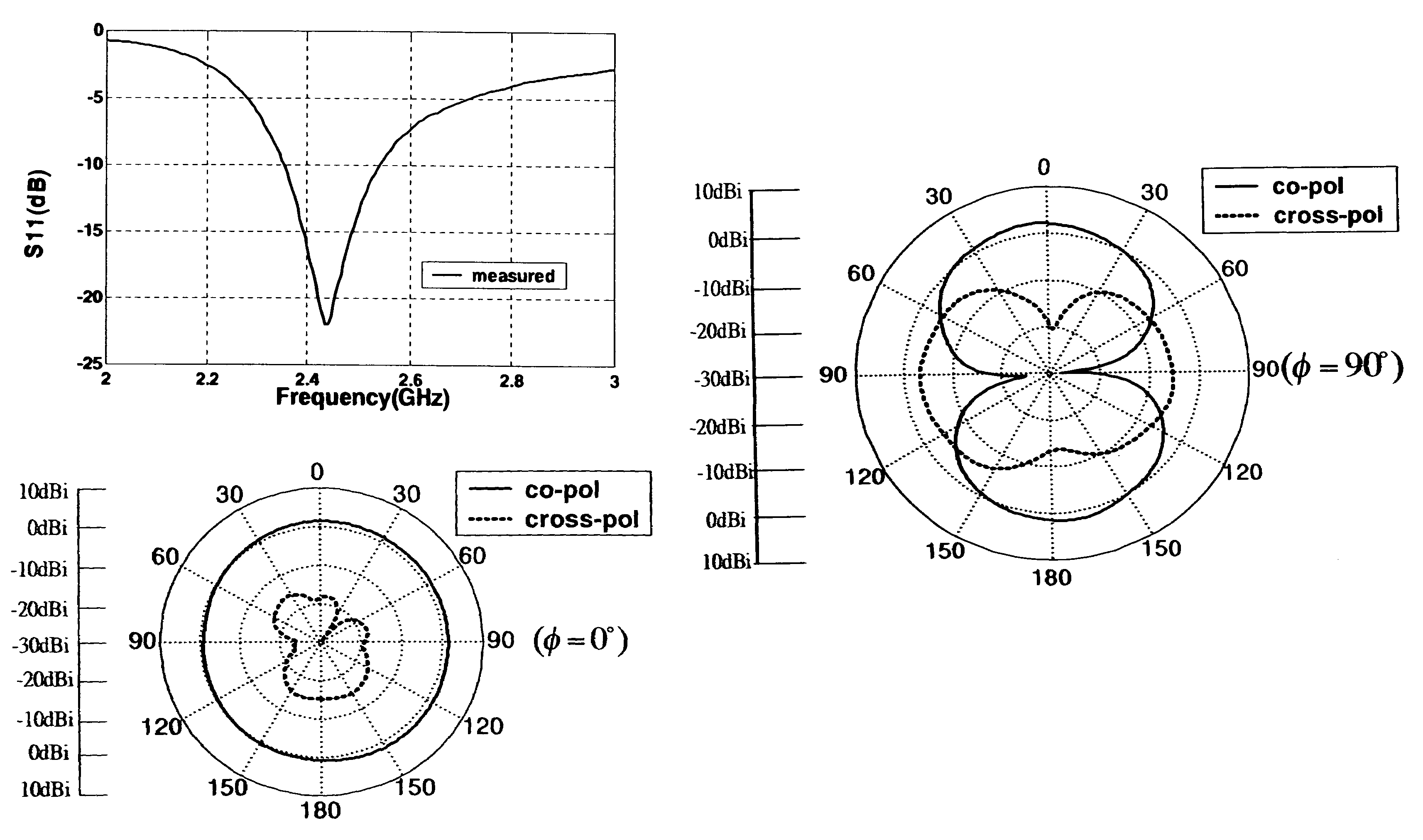
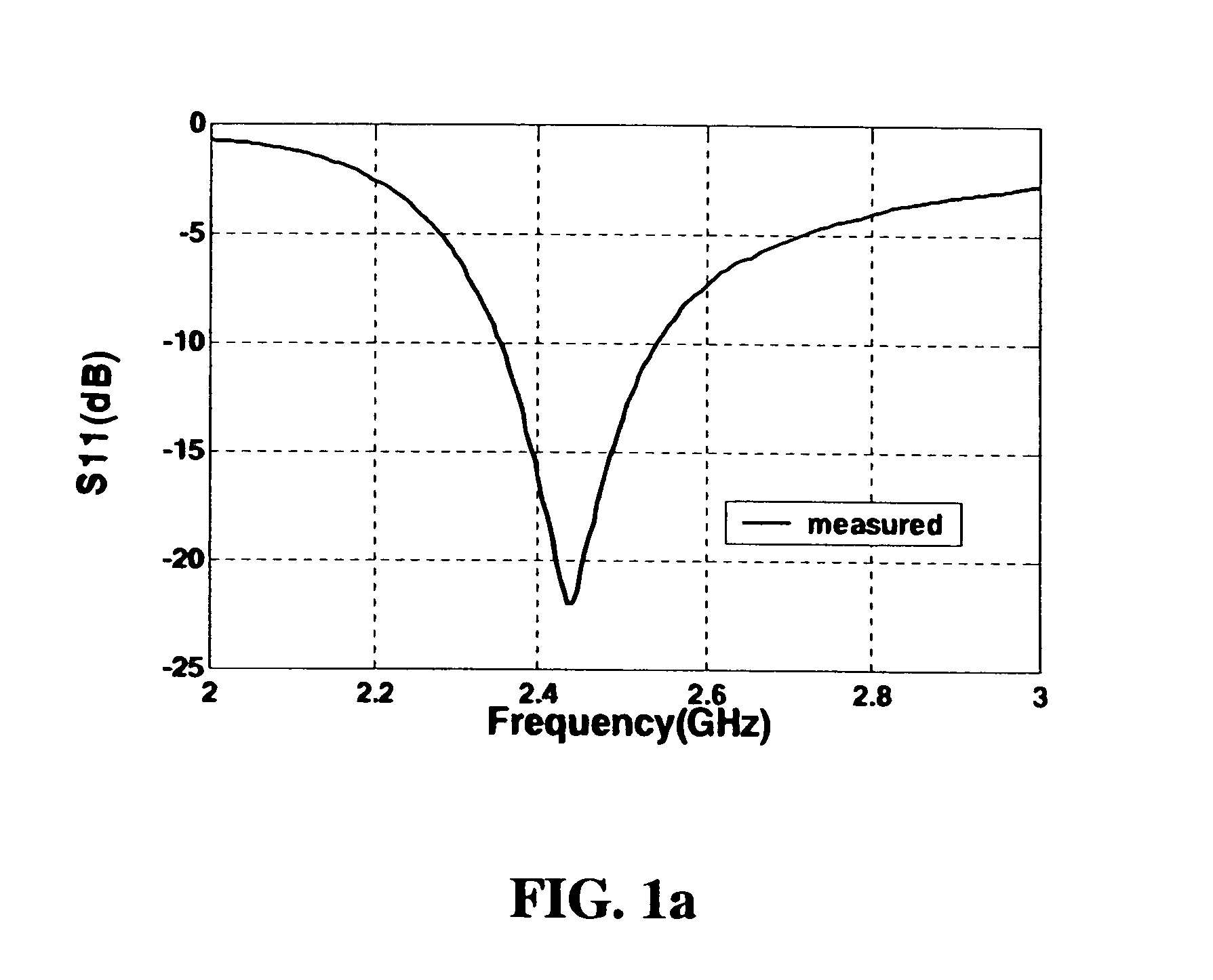
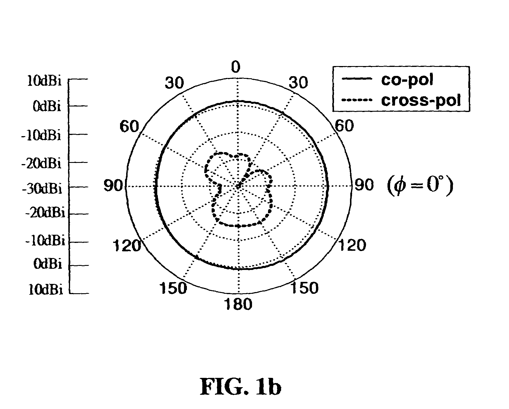
[0019]Please refer to FIG. 2a, which is a schematic diagram showing a planar notch antenna according to an embodiment of the present invention. The present embodiment is implemented by etching a notch antenna 20 on the ground side 10 of a FR4 circuit board (not numbered) having a thickness of 0.8 mm. The notch antenna 20 has a short-circuited end 22 and an open-circuited end 24. Theoretically, such a notch antenna could have a total length smaller than ¼ of the center wavelength of the notch antenna's targeted frequency band. Using the ISM band around 2.45 GHz as example, a notch antenna for this band could have a total length smaller than 22 mm. To further reduce its dimension, the present embodiment bends the no...


PUM


Abstract

A miniature antenna for various wireless communication applications in the ISM band around 2.45 GHz is provided. The miniature antenna mainly contains a bended planar notch antenna with a metallic stub as a capacitive load. A microstrip feed line is also appropriately bended so as to achieve a significant reduction of the antenna's dimension. The miniature antenna could be implemented using simple manufacturing processes on a common circuit board without mechanical work or advanced processes such as low temperature co-fired ceramics. The antenna has a comparable performance to those antennas having much larger dimensions.

Description

BACKGROUND OF THE INVENTION[0001]1. Field of the Invention[0002]The present invention generally relates to antennas, and more particularly to a miniature planar notch antenna using microstrip feed line.[0003]2. The Prior Arts[0004]As mobile communications are gaining widespread popularity, device vendors are continuously squeezing complicated functions such as picture taking, video recording, MP3 playback, FM receiving, Internet connectivity, and even fingerprint identification into the already crowded mobile devices such as PDAs and handsets. As such, the antenna of these mobile computing or communications devices, as one of the most vital components, is required to scale down as much as possible without sacrificing its performance.[0005]The industrial and academic arenas have been working on miniature antenna for some time already. The commonly known approaches include, for example, patch antenna using shorting pins, patch antenna with slot, antenna using meander patch, etc. Among...

Claims


Application Information

Patent Timeline
Patent Type & Authority Patents(United States)
IPC IPC(8): H01Q13/10
CPCH01Q1/243H01Q13/16H01Q13/106
Inventor LI, CHING-LIEHCHANG, JIAN-PING
Owner TAMKANG UNIVERSITY
Why Eureka
Try Eureka