
Heat scavenging method for thermal recovery process

Active Publication Date: 2014-08-07
CONOCOPHILLIPS CO
View PDF12 Cites 25 Cited by
  • Summary
  • Abstract
  • Description
  • Claims
  • Application Information

AI Technical Summary

Benefits of technology

The patent describes a method for improving steam-based oil recovery by injecting steam and solvent into an injection well and recovering produced hydrocarbons from a production well. The improvement involves injecting steam into the injection well until the cost of production exceeds a certain level. Then, a lower quality steam, a foaming agent, and optionally a gas are injected to scavenge heat from a depleted steam chamber and generate steam in-situ, thus reducing the overall cost of production.

Problems solved by technology

The heavier crudes present a dilemma for the economics of petroleum development.
However, the oil recovery factors for heavy oil are often limited to about 5-30% of the original oil in place, and the recovery costs are very high due to the extreme viscosity of the oil and its chemical makeup.
Fireflood projects are not extensively used due to the difficultyin controlling the flame front and a propensity to set the producing wells on fire.However, the method uses less freshwater, produces 50% less greenhouse gases,and has a smaller footprint than other production techniques.COGDCombustion Overhead Gravity Drainage is another ISC method that employs a numberof vertical air injection wells above a horizontal production well located at the base ofthe bitumen pay zone.
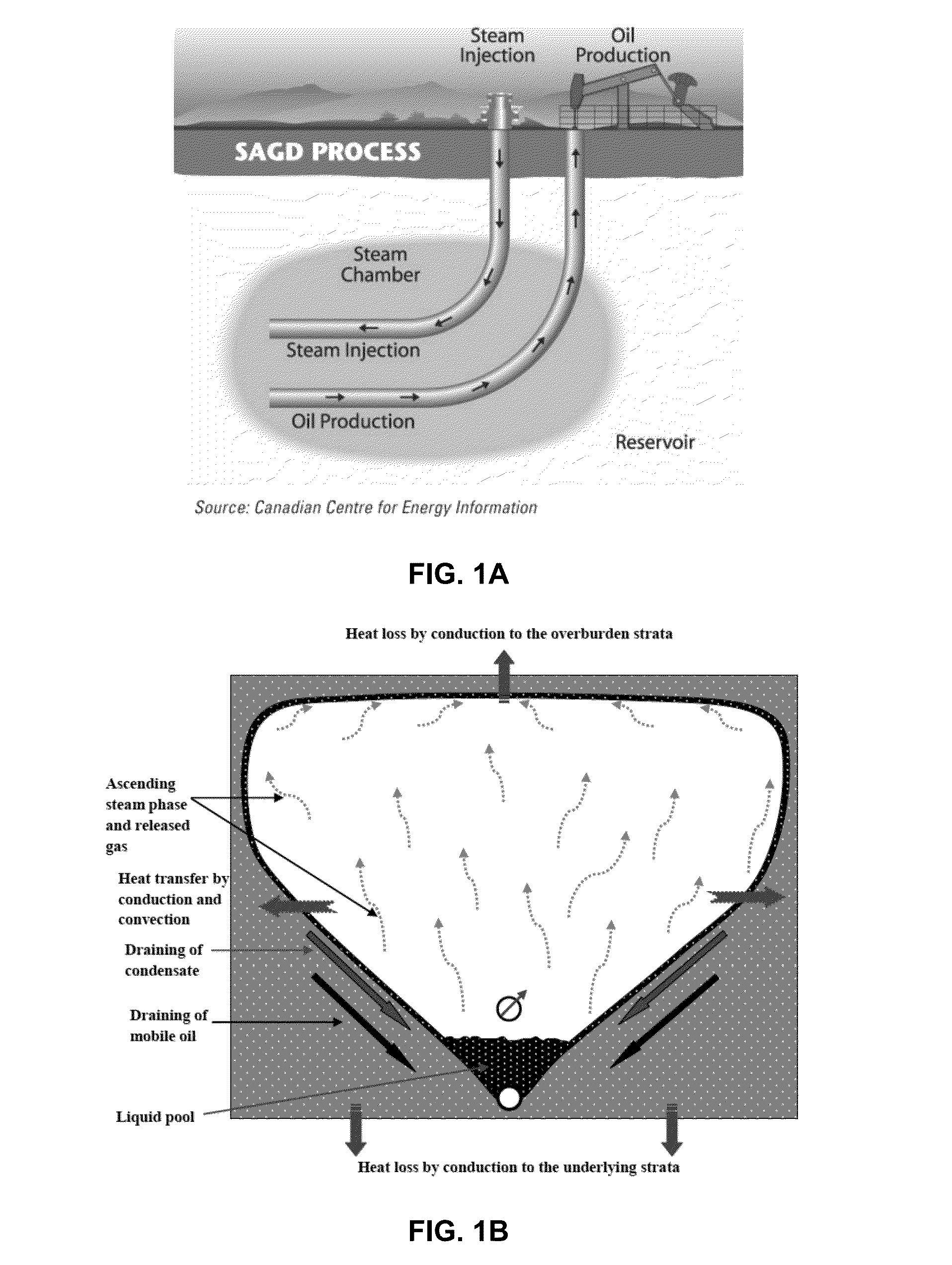
However, the high production rate of the SAGD process is also associated with intensive energy consumption and CO2 emissions from burning natural gas to generate steam, as well as costly post-production water purification treatment and separation of the water from the production fluid.
Further contributing to costliness, much of the energy used is wasted in SAGD and other steam-based methods.
In fact, some estimate that on average, one third of the energy injected is produced back with fluids, one third is lost to the over-burden and under-burden rock, and one third is left in the depleted portion of the reservoir after abandonment.
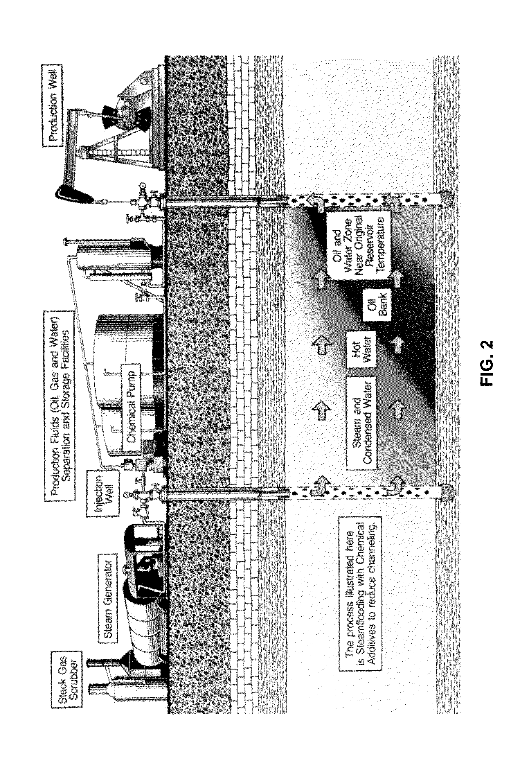
Another source of inefficiencies in steam-based EOR methods is caused by preferential channeling of the steam and / or water directly to the production well.
After steam has been injected for some period of time, oil swept areas have increased permeability and these areas of high permeability tend to act as steam thieves.
Even though all of the above discuss using a foaming agent with steam, none of these discuss the possibility of using a foaming agent together with a low quality steam or hot water to optimize the steam based recovery methods by scavenging any heat that is lost during the process.

Method used


Image

  • Heat scavenging method for thermal recovery process
  • Heat scavenging method for thermal recovery process
  • Heat scavenging method for thermal recovery process

Examples


Embodiment Construction

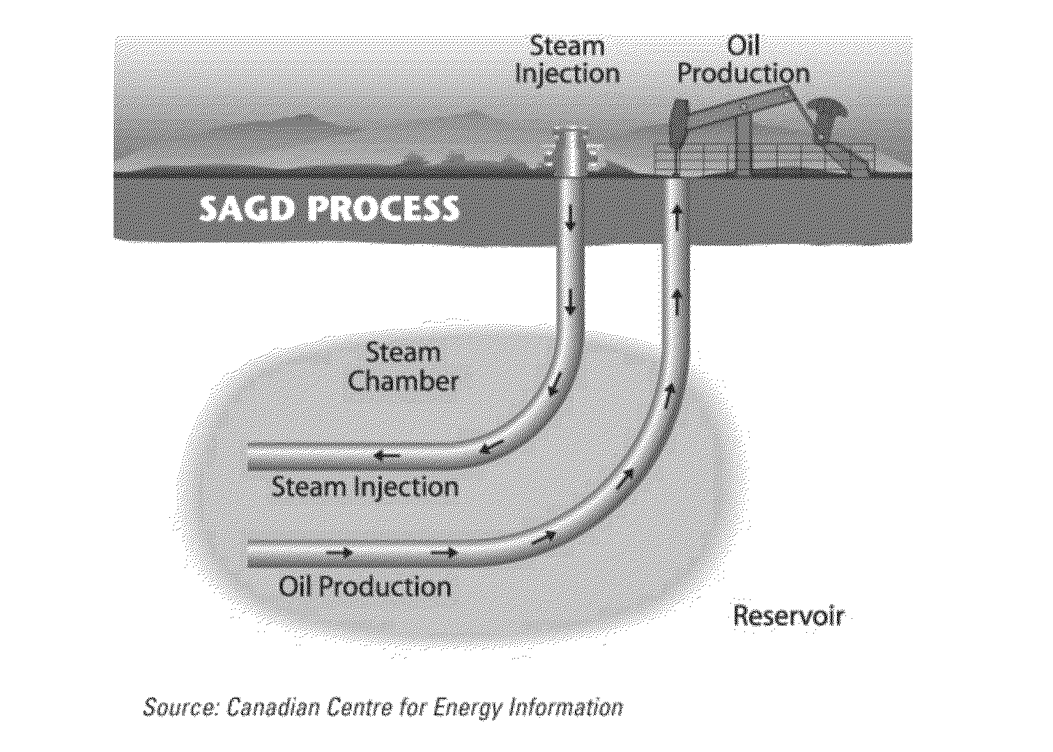
[0037]The disclosure relates to a heat scavenging method using an agent for forming foams / aerosols / hydrosols / other emulsions or colloidal dispersions, which can be abbreviated FHS for foam heat scavenging, herein. In some embodiments, the foams / aerosols / hydrosols / other emulsions or colloidal dispersions form above ground and injected instead of forming in situ.

[0038]This FHS invention will prolong the working life of the thermal recovery methods and increase oil production by allowing the use of low quality steam or hot water, a composition (such as a foaming agent, used hereafter for exemplary purposes only given possibility of creating the aerosols / hydrosols / other emulsions or dispersions) for the FHS, and optionally a gas to generate a foam that can capture the residual heat stored in the depleted portion of the reservoir to create in situ steam that will then be used to further recover bitumen.

[0039]The process will reduce the amount of energy left behind in the reservoir by uti...


PUM


Abstract

Thermal recovery of oils is improved by capturing waste heat from a depleted steam chamber using steam plus foam and an optional gas to carry low quality steam deep into the chamber where the waste heat converts water to steam in situ. Thus, overall steam generation needs and thus costs are reduced.

Description

CROSS-REFERENCE TO RELATED APPLICATIONS[0001]This application is a non-provisional application which claims benefit under 35 USC §119(e) to U.S. Provisional Application Ser. No. 61 / 750,248 filed Jan. 8, 2013, entitled “HEAT SCAVENGING METHOD FOR THERMAL RECOVERY PROCESSES,” which is incorporated herein in its entirety.FEDERALLY SPONSORED RESEARCH STATEMENT[0002]Not applicable.FIELD OF THE INVENTION[0003]The invention relates to a method of enhancing steam production of heavy oil, in particular to a method of improving recoveries and improving thermal efficiency by reducing steam and energy usage through the sweeping of the steam chamber with a low quality steam or hot water and foam combination. The low quality steam or hot water and foam combination carries water to the rock, that has been heated by the steam, and thus recaptures the waste heat therein and forms steam in situ, and driving production beyond what would normally be economical. Since less steam is used, the process is ...

Claims


Application Information

Patent Timeline
IPC IPC(8): E21B43/24
CPCE21B43/2408E21B43/16C09K8/592C09K8/94
Inventor BROWN, DAVID A.WICKRAMDTHILAKA, SILUNI L.WARREN, LOGAN A.WHEELER, THOMAS J.GOVIND, PRADEEP A.
Owner CONOCOPHILLIPS CO
Learn More