

Salt-resistant hydrophobically modified copolymer nanostructures as viscosity increasing agents for enhanced oil recovery
- Summary
- Abstract
- Description
- Claims
- Application Information
AI Technical Summary
Benefits of technology
Problems solved by technology
Method used
Image

Examples
Embodiment Construction
[0024]In the following detailed description, various examples are presented to provide a thorough understanding of inventive concepts, and various aspects thereof that are set forth by this disclosure. However, upon reading the present disclosure, it may become apparent to persons of skill that various inventive concepts and aspects thereof may be practiced without one or more details shown in the examples. In other instances, well known procedures, operations and materials have been described at a relatively high-level, without detail, to avoid unnecessarily obscuring description of inventive concepts and aspects thereof.
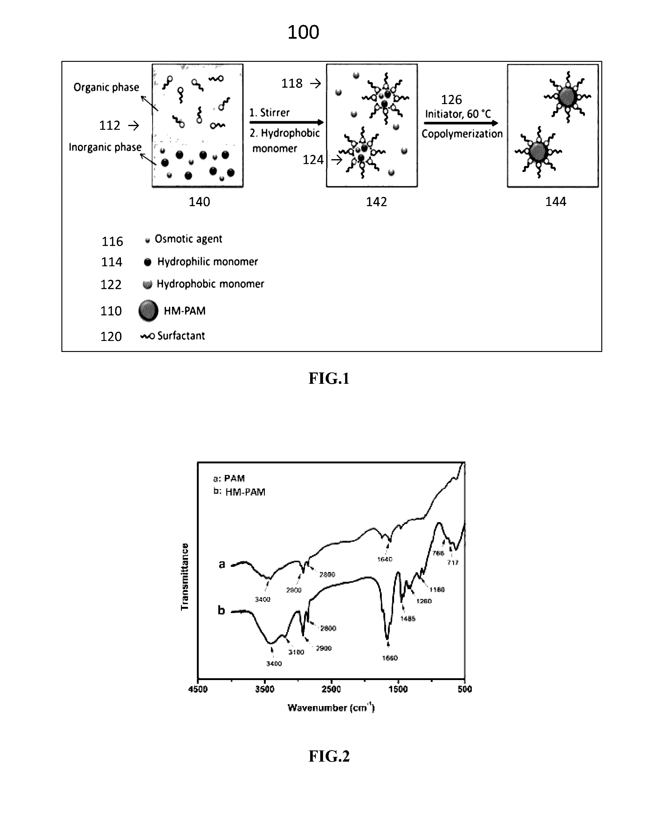
[0025]In traditional polymer flooding, a high viscosity polymeric solution, including hydrophilic polymer (for example, HPAM and PAM) and water, is injected into underground reservoirs by high viscosity pumps. The injecting can be after water flooding and its fingering phenomenon. This solution is injected to propagate through the water phase and control the mobili...
PUM
| Property | Measurement | Unit |
|---|---|---|
| Diameter | aaaaa | aaaaa |
| Boiling point | aaaaa | aaaaa |
| Boiling point | aaaaa | aaaaa |
Abstract
Description
Claims
Application Information