Crank Assembly

Inactive Publication Date: 2014-08-07
LANDAU SERGIO
View PDF2 Cites 2 Cited by
  • Summary
  • Abstract
  • Description
  • Claims
  • Application Information

AI Technical Summary

Benefits of technology

[0007]One embodiment of the invention is a crank assembly designed to allow the length of the crank arms to vary throughout the revolution of the crank. The invention is designed such that it can be used with existing vehicles, or machines. One example of such a vehicle, or machine, is a bicycle, however the invention may also be used with other crank driven machines. First, a crank arm assembly is attached to the bicycle's existing spindle assembly. The crank arm assembly comprises a mounting section, rail section, and sliding section. The crank arm assembly includes a rail section that is fixed at one end to the mounting section of the crank arm assembly. The rail section comprises a predominately solid piece of material with smooth bearing surfaces. Next, the opposite end of the rail section is attached to the sliding section of the crank arm assembly. The sliding section of the crank arm assembly also includes features that allow the sliding sect

Problems solved by technology

However, the crank system with fixed-length crank arms is not optimally efficient.
However, for uphill, rough terrain, mountain bike riding, or whenever there is a gain in elevation, bicycles with fixed-length crank arms b

Method used


Image

  • Crank Assembly
  • Crank Assembly
  • Crank Assembly

Examples


Embodiment Construction

[0023]The following describes the details of the invention. Although the following description will proceed with reference being made to illustrative embodiments, many alternatives, modifications, and variations thereof will be apparent to those skilled in the art. Accordingly, it is intended that the claimed subject matter be viewed broadly. Examples are provided as reference and should not be construed as limiting. The term “such as” when used should be interpreted as “such as, but not limited to.”

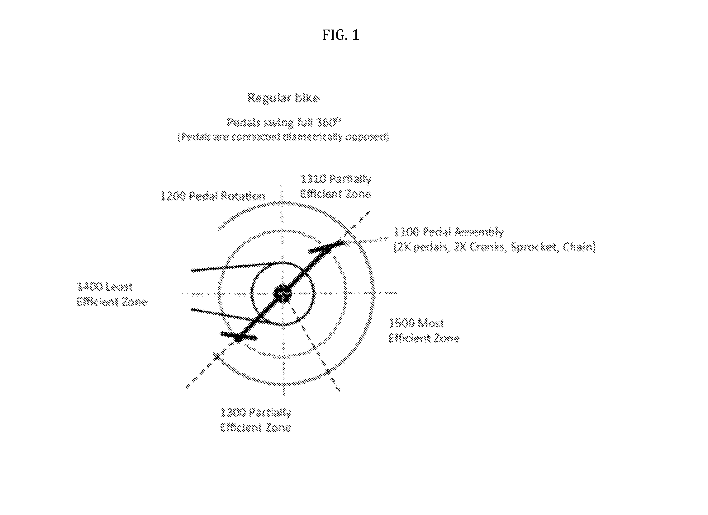
[0024]FIG. 1 illustrates the efficiency of a pedal swing of a regular crank assembly 1100 with fixed-length crank arms. A regular bike includes a pedal swing that encompasses three hundred and sixty degrees with a diametrically opposed pedal assembly 1100. Approximately one hundred and five degrees of a pedal swing is only partially efficient, as represented by the partially efficient zones (1310 and 1300). In these partially efficient zones approximately 30% of the total torque generate...


PUM


Abstract

This invention provides a novel solution for an optimally powered crank for a human-powered vehicle, such as a bicycle. This invention includes a novel system and method to optimize the length of each crank arm throughout the revolution of the crank assembly. First, a crank arm assembly is attached to the bicycle's existing spindle assembly. The crank arm assembly includes a rail section that is fixed at one end to the mounting section of the crank arm assembly. Next, the opposite end of the rail section is attached to the sliding section of the crank arm assembly. The sliding section of the crank arm assembly also includes a feature that allows the sliding section to collapse and expand along the rail section. The crank arm assembly also includes at least two track rollers mounted to the side of each sliding section designed to reduce friction and counter inertial forces associated with the crank arm assembly sliding along the tracks. Next, the assembly includes two tracks mounted on each side of the frame. The tracks are used to control the length of the crank arms at each angular position. Finally, the shape of each track is designed to coincide with the optimum crank arm length at the various angular positions as the crank arm rotates through a complete revolution.

Description

CROSS-REFERENCE TO RELATED APPLICATIONS[0001]The present application is related to and claims priority from prior provisional application Ser. No. 61 / 761,216 filed Feb. 5, 2013 the contents of which are incorporated herein by reference.FIELD OF THE INVENTION[0002]This invention is in the field of human powered machines, and in particular a crank assembly, such as a crank assembly for bicycles.BACKGROUND OF THE INVENTION[0003]Human-powered machines, such as bicycles, have played important roles in human lives since the invention of the wheel. Various forms of human-powered cycles, such as bicycles, tricycles, and scooters are used every day for recreation and work in just about every society throughout the world. Even a small enhancement that results in weight reduction, size reduction, cost reduction, increased energy conversion, increased speed, or ease of use will have a drastic impact.[0004]The basic design of a bicycle consists of a frame, a pair of wheels, a steering mechanism,...

Claims


Application Information

Patent Timeline
IPC IPC(8): B62M3/04
CPCB62M3/04B62M3/02Y10T74/2164
Inventor LANDAU, SERGIO
Owner LANDAU SERGIO
Why Eureka
Try Eureka