Vehicle seat apparatus for collision injury prevention

a technology for vehicle seats and collision injuries, applied in the field of seats, can solve the problems of disc herniation, nerve root damage, soft tissue fiber tear, shearing and inflammation of the supporting structure of the spine, etc., and achieve the effects of increasing the ability of airbags, reducing the risk of injury, and increasing density

Inactive Publication Date: 2014-08-07
NORWOOD MICHAEL
View PDF0 Cites 13 Cited by
  • Summary
  • Abstract
  • Description
  • Claims
  • Application Information

AI Technical Summary

Benefits of technology

[0026]Airbag: In addition, an impact-absorbing mechanism is used in the airbag as well to increase the ability of the airbags to shield the front seat occupant and driver from injury due to whiplash as compared to prior art air bags. The airbag device affixed to the vehicle dashboard and steering wheel comprises multiple layers of material of increasing density, resiliency, and impact absorption in the orientation of the occupants to the dashboard and steering wheel. In one embodiment, the multiple l...

Problems solved by technology

Whether the collision is front or rear-end, the result is a tearing, shearing and inflammation of soft tissue fibers found in the supporting structures of the spine.
If the tearing and inflammation of the annular fibers of the disc is great enough, disc nuclear protrusion will result and possible disc herniation.
Either can result in nerve root damage and subsequent radicular neuropathy—mainly pain or numbness along the entire nerve tract extending into the arm, hands and fingers.
In the most severe of such acceleration/deceleration injuries, paralysis can result, and sometimes death.
In addition to the nerve, spinal cord and soft tissue damage which can be caused by even relatively low impact rear-end or front-end collisions of as little as a few mph, brain damage can result as well.
However, in any acceleration/deceleration injury, the brain is propelled forward and backward into the hard bone causing swelling and potential damage to brain tissue.
However, neither prevent the “whiplash” and “contre-coup” type of damage caused by the violent front-back-front or back-front-back acceleration/deceleration of head and neck movement.
Prior art disclosures...

Method used


Image

  • Vehicle seat apparatus for collision injury prevention
  • Vehicle seat apparatus for collision injury prevention
  • Vehicle seat apparatus for collision injury prevention

Examples


second embodiment

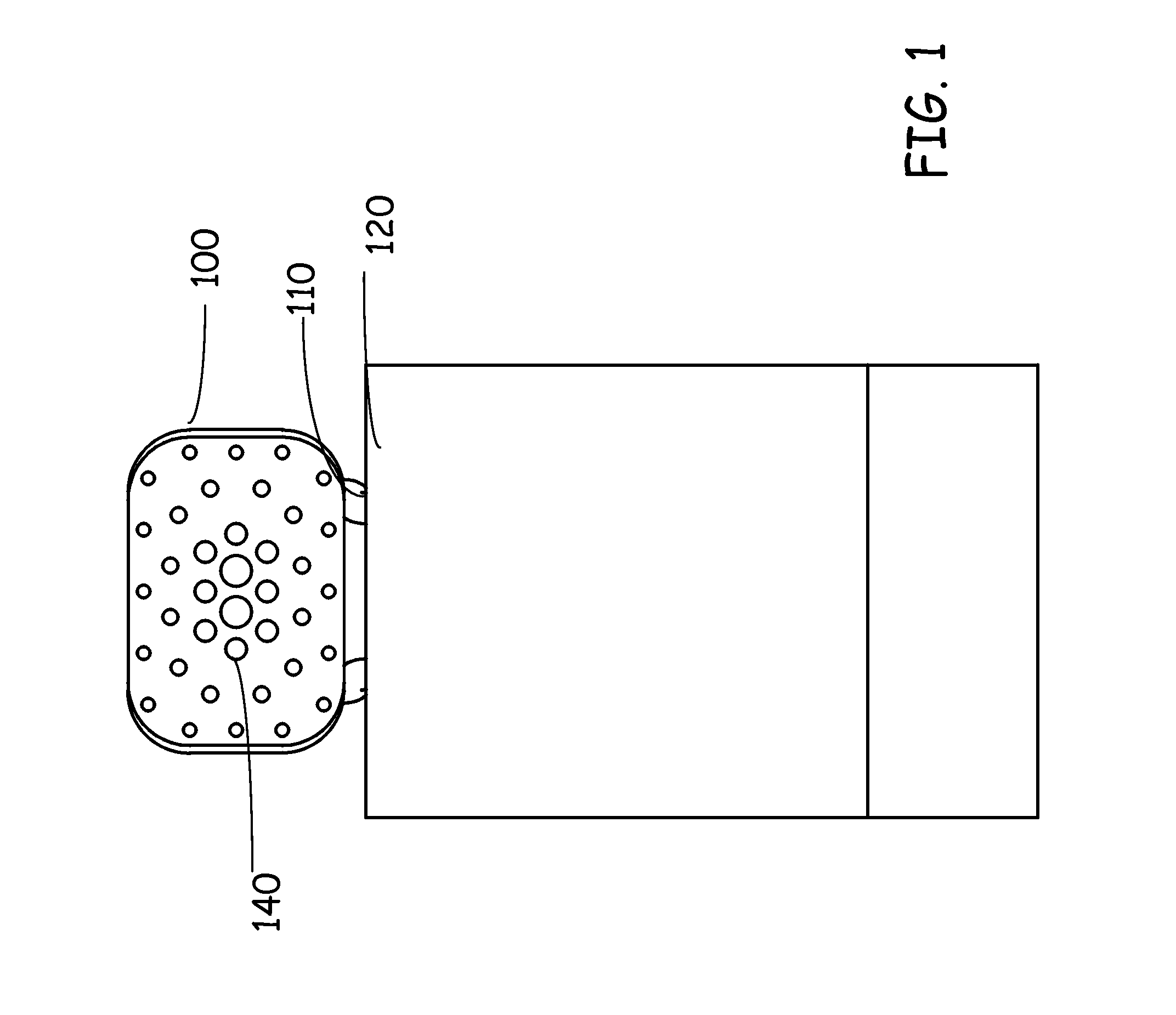
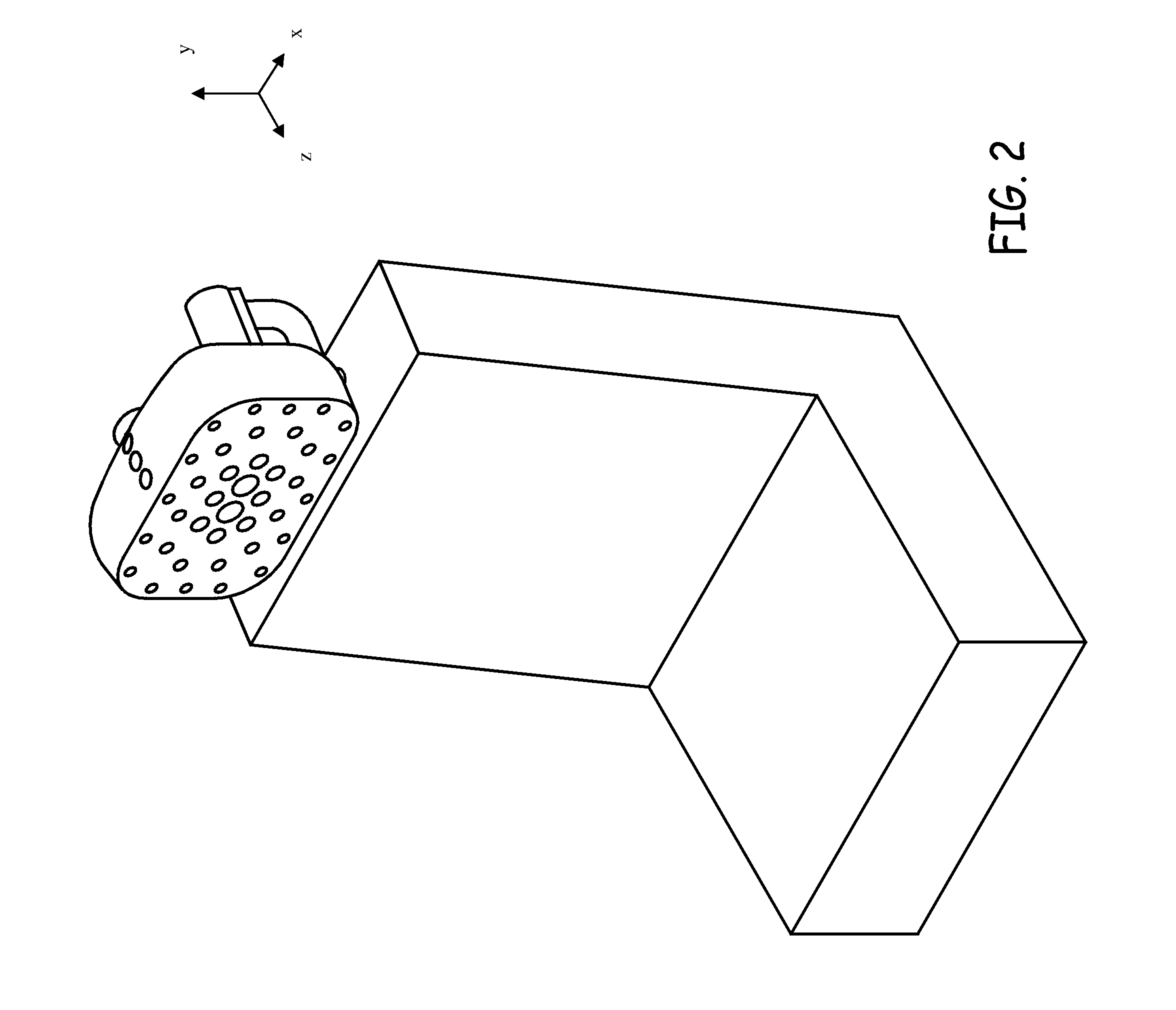
[0053]FIGS. 6-10 illustrate the headrest comprising a pattern of holes of uniform diameter and density from the center to the outer periphery on the front surface of the headrest. The holes may further extend through the thickness of the headrest from the front surface to the back surface, and the channels created by the holes may be of uniform diameter to create cylindrical channels, or they can be of decreasing diameter through the headrest to create conical channels that radiate outward from the center of the headrest. As in the previous embodiment, the channels may go entirely through the headrest or almost through.

[0054]FIG. 6 is an overhead front perspective view of the headrest with the holes 140 of uniform diameter along the face of the headrest, and multiple rows of vertical channels 150 along the center of the headrest. FIG. 7 is a front view of the same headrest with a line “8” on the x-axis to represent the overhead cross-sectional view as shown in FIG. 8, and a line “10...

first embodiment

[0062]FIGS. 23-27, 28A and 28B illustrate a first embodiment where the shock absorption mechanism is positioned on the back of the headrest, and comprises an apparatus 110 with four points of connection (i.e. two to the headrest 100 and two to the top of the seatback 120) utilizing two identical or mirrored members (112, 114). The shock absorber means allows for backward movement of the headrest along the horizontal plane (x, z axis) to absorb impact forces (−z direction—backward) while diminishing opposing rebound forces (+z direction—forward) in order to slow the speed and the distance of the occupant's head / neck backward then forward movement (i.e. recoil).

[0063]The disclosure's headrest / seatback connection in some embodiments may be angled at greater than 90 degrees in the horizontal plane into the headrest. (This angling can be used in any embodiment of the disclosure, including those described below.) This horizontal plane angling accomplishes two things. First, in the C-shape...

third embodiment

[0070]As illustrated in FIGS. 36A and 36B, the third embodiment comprises the apparatus 500 sitting between lower surface of the headrest and the top surface of the seatback, and attaching to the seatback via one to four vertical members (e.g. rods) 510, comprising two rods aligned in the y, z-axis on the right and left side of the apparatus. The headrest is directly attached to the lever 520 which has an internal torus 530 encasing the spring 540 (e.g. compression or torsional helical spring) and an external torus 550 encased by the spring. Internal torus 530 is attached to apparatus 500. Lever 520 can rotate around axis 525. Axis is attached to apparatus 500. This disclosure absorbs impact on both the horizontal and vertical planes. In alternate embodiments, air or oil-based shock absorbing mechanism can be used in a similar manner.

Vertical Headrest / Seatback Shock Absorber Apparatus


PUM


Abstract

A vehicle safety device for decreasing injury to occupants resulting from a collision, comprising enhanced impact absorbing apparatuses: (1) headrests and seatbacks with conical or cylindrical holes and layers of material to absorb impact forces; (2) 4 embodiments of apparatuses attaching the headrests to the seatback comprising shock absorption means to reduce whiplash injuries; (3) spring loaded means of attaching the seat bottom to the vehicle floor to provide the seats recoil mechanisms for collisions from all directions; (4) seatbelts with all points of contact to the seat to provide the seatbelts recoil mechanisms, and comprising gel and/or foam layers and a flexible weave design; (5) seat tilt mechanisms that enable the seat to recoil during a collision; and (6) airbags with multiple layers of material of increasing impact absorption from the occupants to the dashboard and steering wheel.

Description

FIELD OF THE DISCLOSURE[0001]The present invention relates to seats within vehicles comprising a headrest, apparatus attaching headrest to seatback, seatbelt, seat bottom attachment, seatback, and airbag design that are engineered to prevent injuries to occupants as a result of a collision.BACKGROUND OF THE DISCLOSURE[0002]The National Highway Traffic Safety Administration reports there were 5,338,000 vehicular crashes in 20111. Of these crashes, 29,757 were fatal2 and 2,091,0623 caused injury. The most common type of vehicular injury is called acceleration / deceleration injury, or, more commonly whiplash. Approximately 80% of these injuries are caused by rear or front end collisions, which are the prime injuries this disclosure aids in lessening and preventing. 1Source: General Estimate System2Source: Fatal Analysis Reporting System (FARS)3Source: Fatal Analysis Reporting System (FARS)[0003]The mechanism of injury in rear-end collisions is typically the violent whipping backward of ...

Claims


Application Information

Patent Timeline
IPC IPC(8): B60N2/427
CPCB60N2/427B60N2/4228B60N2/42709B60N2/42745B60R21/233B60R21/203B60R2021/23324B60N2/888
Inventor NORWOOD, MICHAELKAPILIOVICH, VIKTOR
Owner NORWOOD MICHAEL
Why Eureka
Try Eureka