

Liquid jet head, method of manufacturing liquid jet head, and liquid jet apparatus
a liquid jet and manufacturing method technology, applied in the direction of piezoelectric/electrostrictive transducers, inking apparatus, transducer types, etc., can solve the problems of increasing manufacturing man-hours, not being able to eject liquid from the nozzle hole, and not being able to apply drive voltage to the drive electrode, so as to increase manufacturing man-hours and reduce costs.
- Summary
- Abstract
- Description
- Claims
- Application Information
AI Technical Summary
Benefits of technology
Problems solved by technology
Method used
Image

Examples
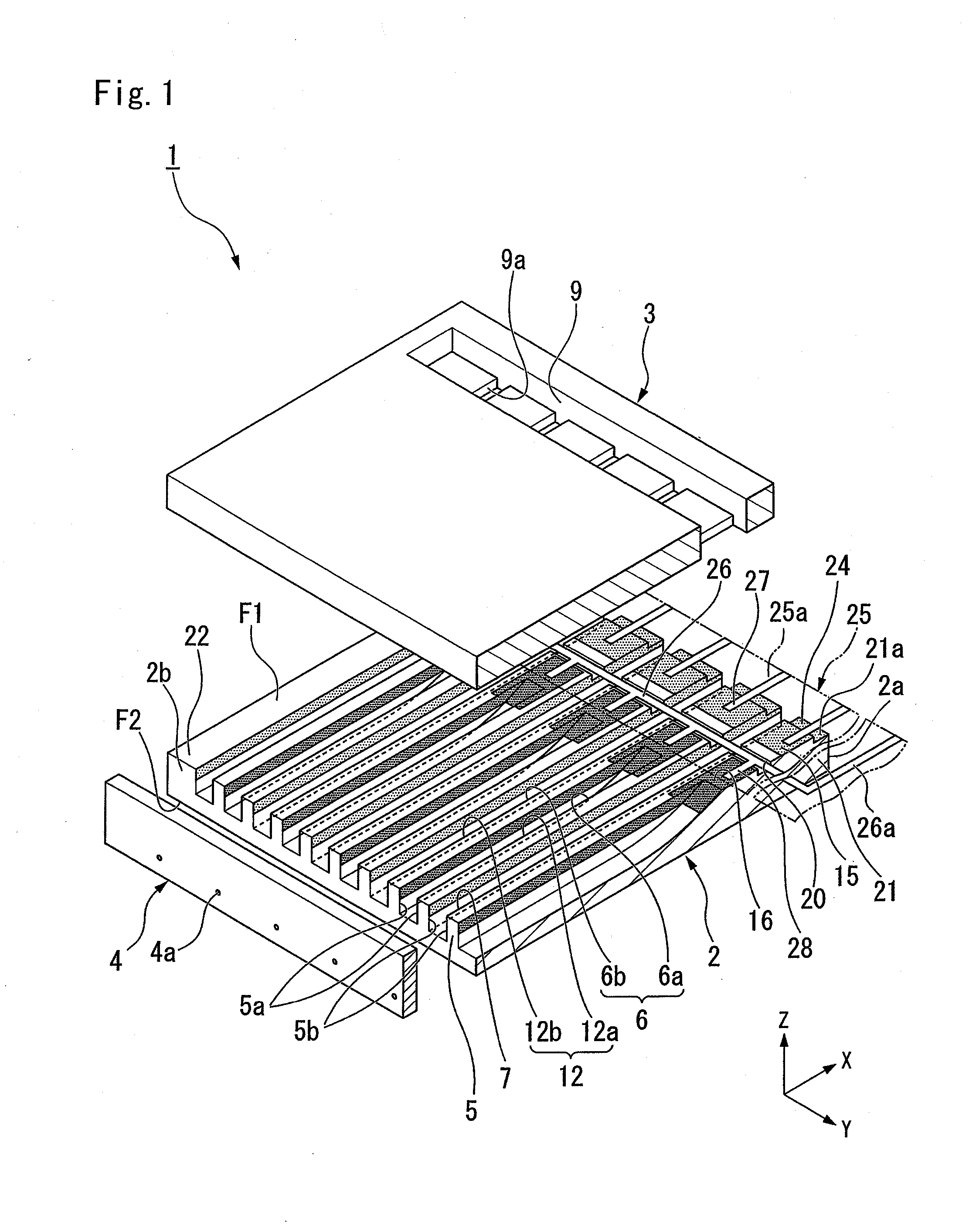
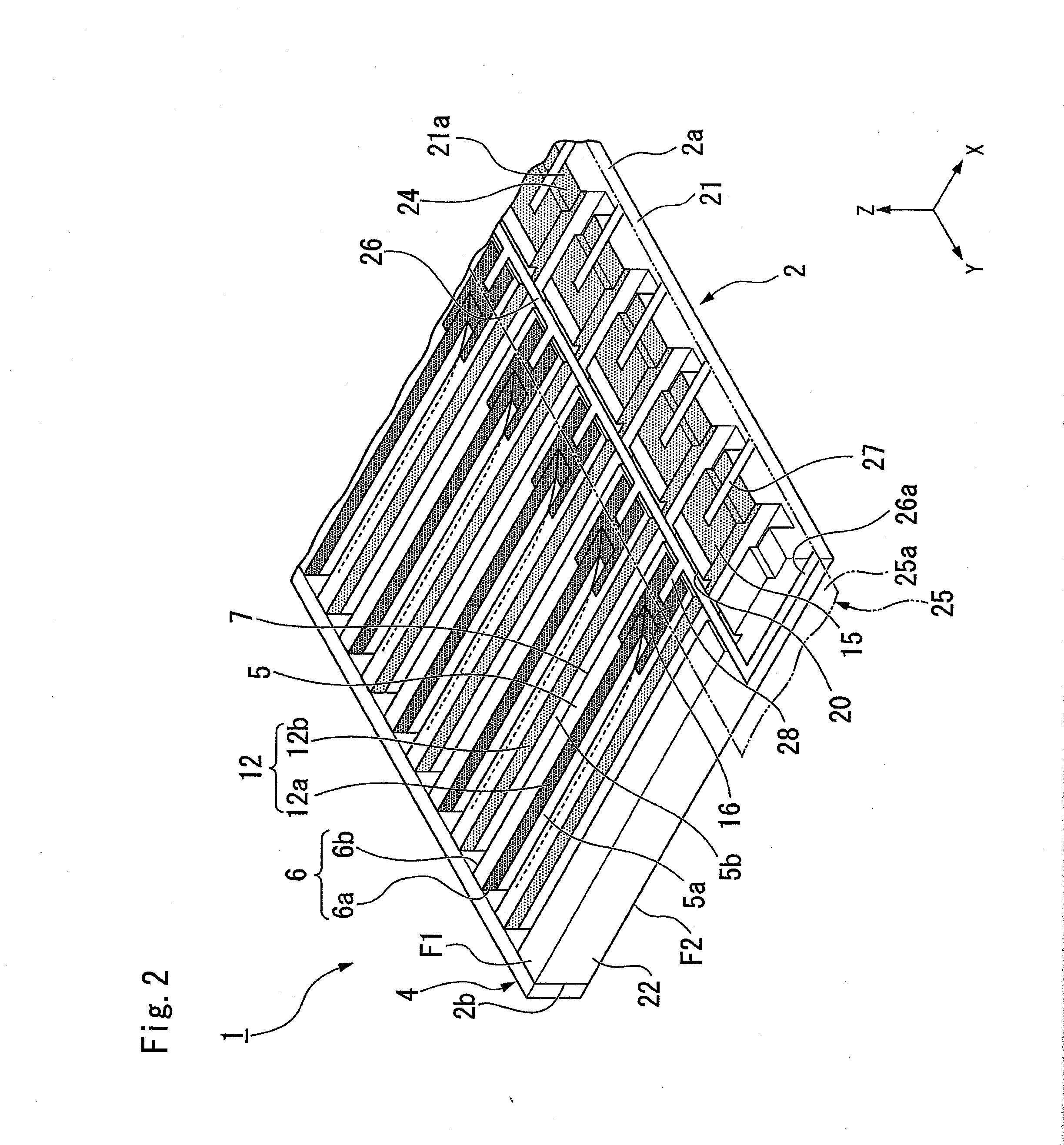
first embodiment
Modified Example of First Embodiment
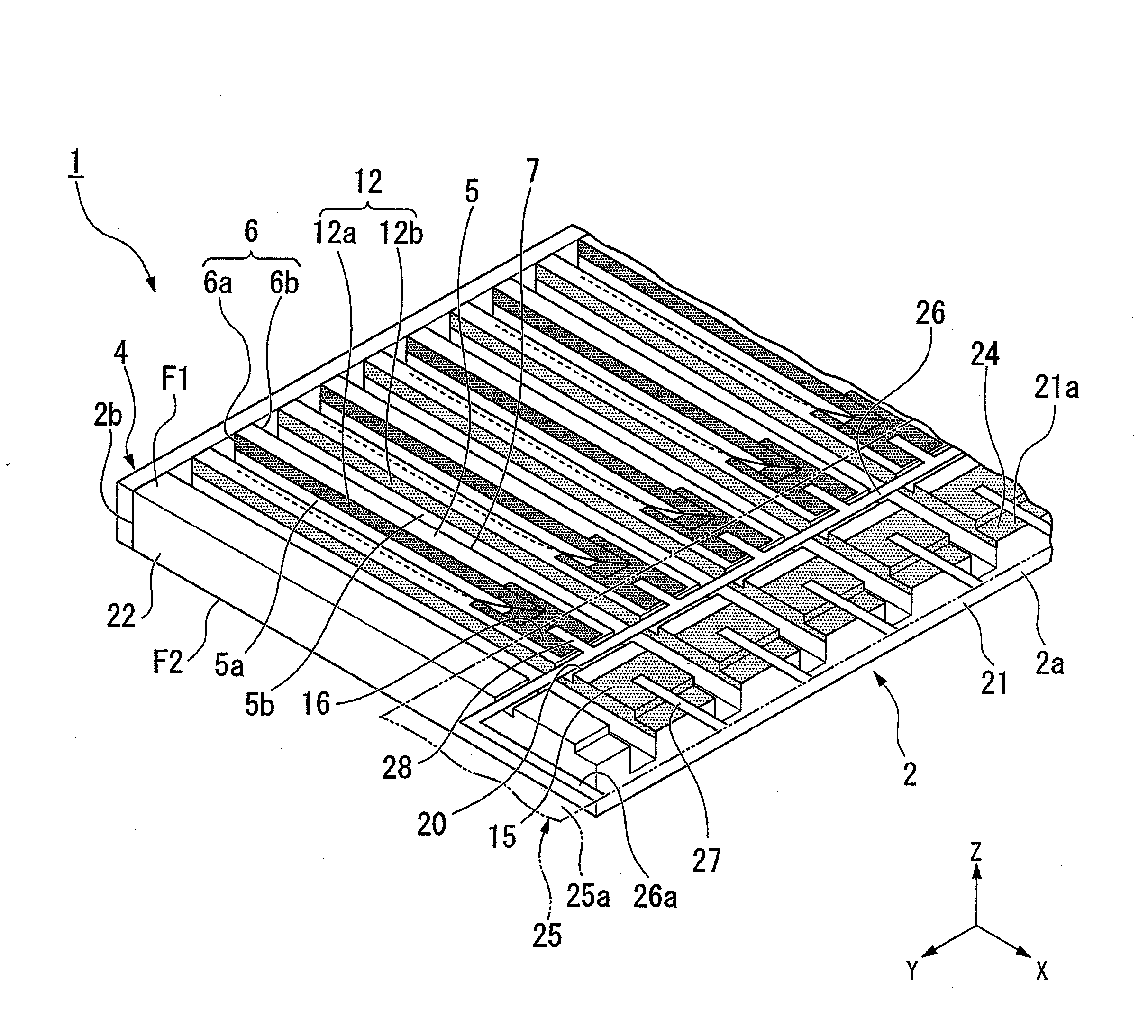
[0113]FIG. 8 is a perspective view of an actuator substrate 2 according to a modified example of the first embodiment.
[0114]Next, the actuator substrate 2 according to the modified example of the first embodiment will be described. Hereinbelow, a description of the same components as those of the first embodiment will be omitted, and only differences from the first embodiment will not be repeated.
[0115]In the actuator substrate 2 of the first embodiment, the individual electrode pads 15 are formed across respective adjacent ones of the non-ejection channels 6b on the first principal face F1 of the actuator substrate 2 (see FIG. 2).
[0116]On the other hand, as illustrate in FIG. 8, in the actuator substrate 2 according to the modified example of the first embodiment, individual electrode pads 15 are formed between respective adjacent ones of the non-ejection channels 6b on the first principal face F1 of the actuator substrate 2. In this manner, a fo...
second embodiment
Effect of Second Embodiment
[0149]According to the second embodiment, the shallow grooves 23 are formed from the +X side ends of the ejection channels 6a toward the +X side end face 2a of the actuator substrate 2. Therefore, when forming the ejection channels 6a, for example, by cutting, the shallow grooves 23 can be formed merely by changing the depth of cutting. Therefore, it is possible to easily form the shallow grooves 23 within the channel forming step S16. Further, the groove 20 is formed so as to intersect the shallow grooves 23. Therefore, the common electrode pads 16 and the individual electrode pads 15 can be easily formed by forming the groove 20 so as to interest the shallow grooves 23, for example, by cutting after forming the film of the electrode material 56 inside the shallow grooves 23 to thereby divide the film of the electrode material 56 formed inside the shallow grooves 23 by the groove 20. In this manner, since the common electrode pads 16 and the individual el...
PUM
| Property | Measurement | Unit |
|---|---|---|
| Width | aaaaa | aaaaa |
Abstract
Description
Claims
Application Information