Backlight module

a backlight module and backlight technology, applied in the field of backlight modules, can solve the problems of inability to unlimitedly shorten the distance between two pegs, and inability to completely eliminate so as to improve the warp of the optic film and enhance the image quality

Inactive Publication Date: 2014-08-07
SHENZHEN CHINA STAR OPTOELECTRONICS TECH CO LTD
View PDF5 Cites 2 Cited by
  • Summary
  • Abstract
  • Description
  • Claims
  • Application Information

AI Technical Summary

Benefits of technology

[0006]An object of the present invention is to provide a backlight module, which effectively prevent an optic film from moving

Problems solved by technology

However, due to general insufficiency of space is available in structure design, it is not possible to unlimitedly shorten the distance between two pegs and the torque caused by gravitational force

Method used


Image

  • Backlight module
  • Backlight module
  • Backlight module

Examples


third embodiment

[0042]Referring to FIGS. 11 and 12, the present invention is shown. In the instant embodiment, the elastic members 7″ are of a U-shape having two second sidewalls that comprise a helical configuration formed in an end portion thereof remote from mounting holes 72′.

fourth embodiment

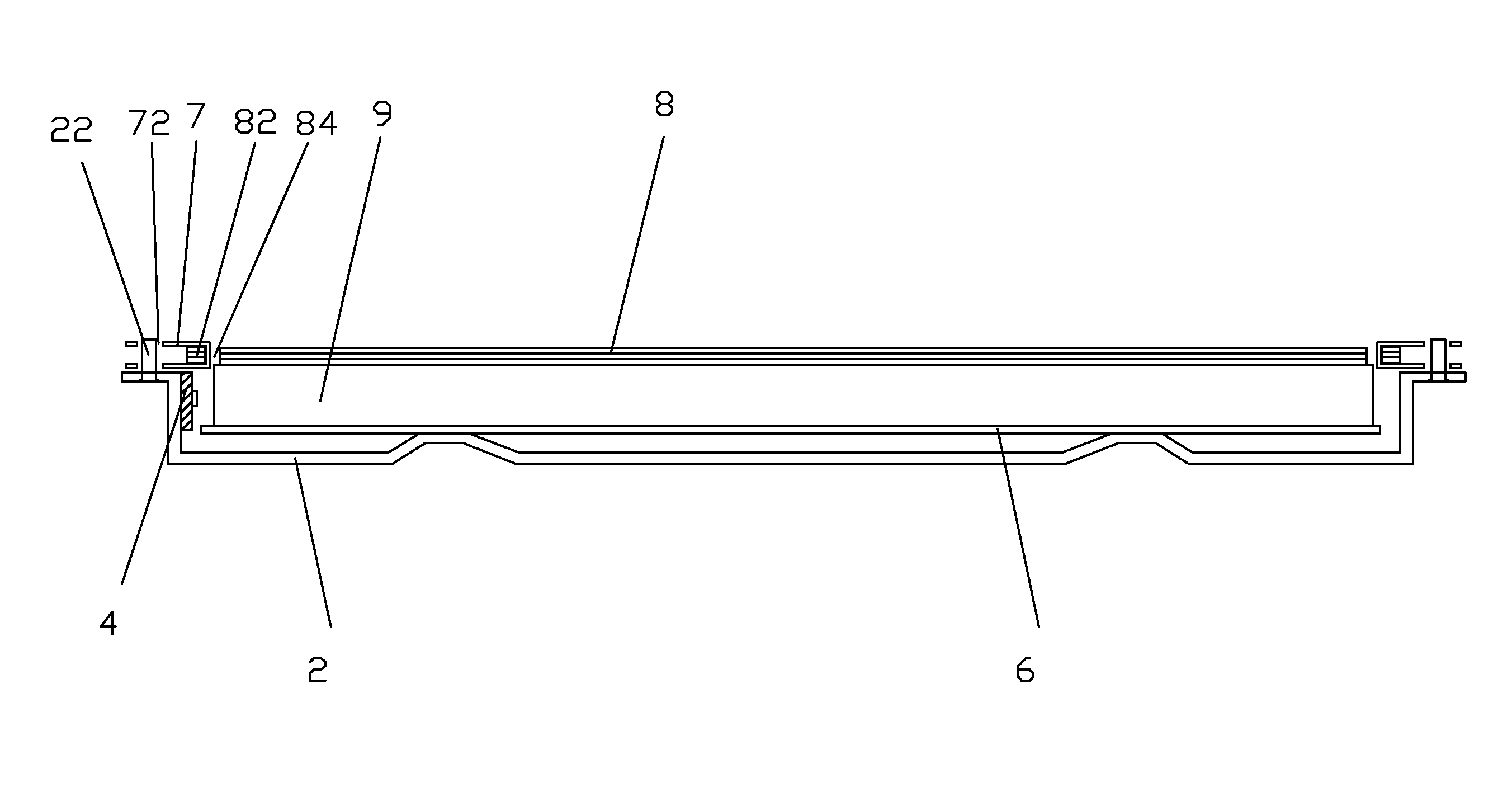
[0043]Referring to FIGS. 13 and 14, the present invention is shown, in which an elastic member 7′″ comprises a bottom plate 77 and two third sidewalls 76 perpendicularly mounted to the bottom plate 77. The two third sidewalls 76 are mutually perpendicular and an opening 79 is formed in a connection between them so as to allow the two third sidewalls 76 to be deflected frontward / rearward or leftward / rightward. The two third sidewalls 76 are arranged to be linear and each has an upper edge forming a second barb 762. The second barb 762 is shaped and sized to correspond to a second through hole 84 of the optic films 8. The bottom plate 77 forms a third through hole 78 that is circular.

[0044]The backplane 2′ forms a mounting hole (not shown) corresponding to the third through hole 78. A screw 24 is applied to secure the elastic member 7′″ to the mounting hole with the second barbs 762 tightly engaging the second through holes 84 formed in the lug 82 to thereby fix the optic films 8 to t...


PUM


Abstract

The present invention provides a backlight module, which includes: a backplane, a backlight source arranged inside the backplane, a light guide plate arranged inside the backplane to correspond to the backlight source, a reflector plate disposed on a bottom of the light guide plate, an optic film disposed on a top of the light guide plate, and elastic members mounted to the backplane. The optic film has a top edge forming suspension sections and two first sidewalls respectively at left and right sides and each forming lugs. The suspension sections form first through holes. The lugs form second through holes. The backplane forms suspending pegs corresponding to the first through holes. The first through holes are mounted on the suspending pegs and the elastic members securely hold the second through holes and are mounted to the backplane so as to fix the optic films on the light guide plate.

Description

BACKGROUND OF THE INVENTION[0001]1. Field of the Invention[0002]The present invention relates to the field of liquid crystal display, and in particular to retention of optic films in a backlight module.[0003]2. The Related Arts[0004]Liquid crystal display (LCD) has a variety of advantages, such as thin device body, low power consumption, and being free of radiation, and is thus widely used. Most of the LCDs that are currently available in the market are backlighting LCDs, which comprise a liquid crystal panel and a backlight module. The operation principle of the liquid crystal panel is that liquid crystal molecules are interposed between two parallel glass substrates and the liquid crystal molecules are controlled to change direction by application of electricity in order to refract light emitting from the backlight module for generating images. Since the liquid crystal panel itself does not emit light, light must be provided by the backlight module in order to normally display ima...

Claims


Application Information

Patent Timeline
IPC IPC(8): F21V8/00
CPCG02B6/0088G02B6/0035G02F1/133308G02B6/005G02F1/133314G02B6/0073
Inventor TANG, GUOFU
Owner SHENZHEN CHINA STAR OPTOELECTRONICS TECH CO LTD
Why Eureka
Try Eureka