Control device and control method for vehicle

a control device and control method technology, applied in electric vehicles, engine-driven generator propulsion, transportation and packaging, etc., can solve the problems of driver awkwardness and engine braking effect may be temporarily reduced, and achieve the effect of reducing friction torque and temporary braking

Inactive Publication Date: 2014-08-07
TOYOTA JIDOSHA KK
View PDF8 Cites 20 Cited by
  • Summary
  • Abstract
  • Description
  • Claims
  • Application Information

AI Technical Summary

Benefits of technology

[0007]The above inertia travel generates friction torque because the engine revolves due to engagement of the clutch. Accordingly, the engine brak

Problems solved by technology

Accordingly, the engine braking effect may be temporary reduced because the friction to

Method used


Image

  • Control device and control method for vehicle
  • Control device and control method for vehicle
  • Control device and control method for vehicle

Examples


Embodiment Construction

[0022]An embodiment of the present invention will hereinafter be described in detail with reference to drawings.

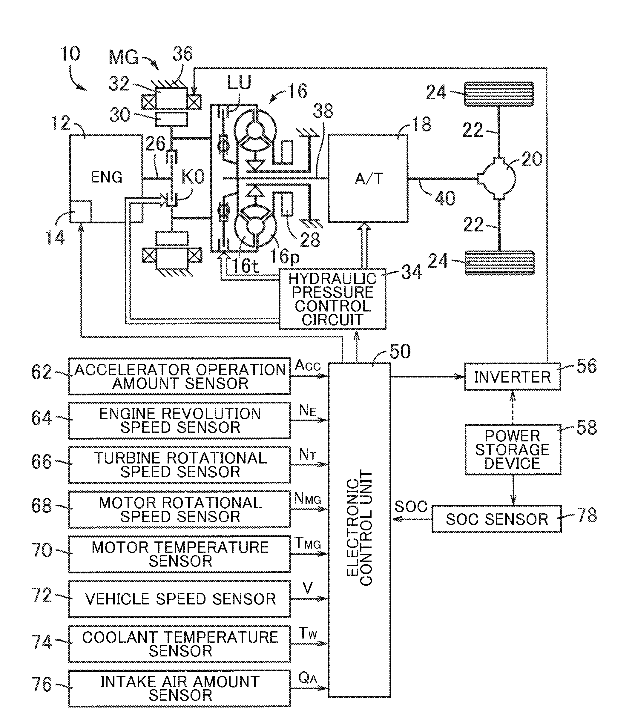
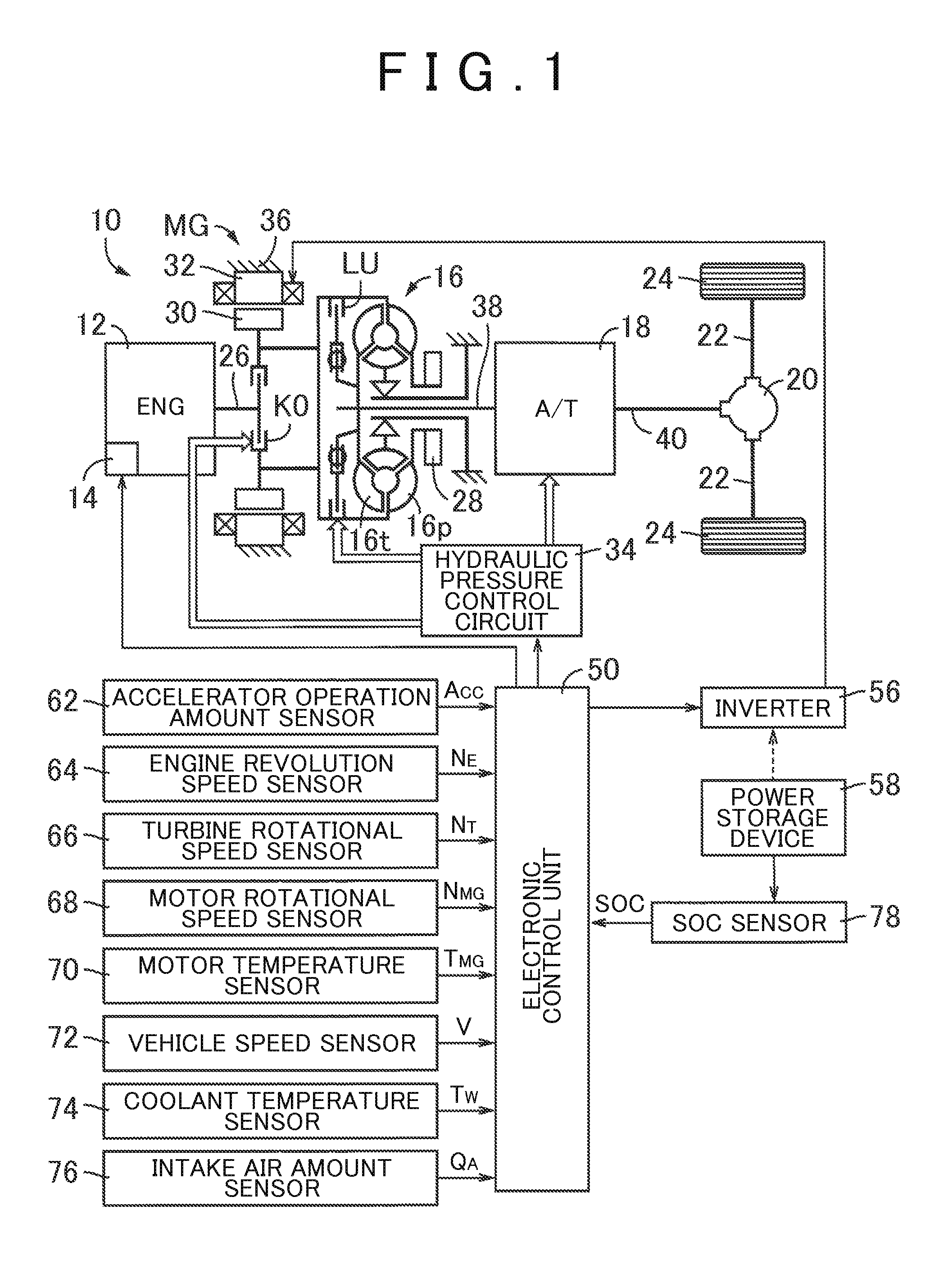
[0023]FIG. 1 conceptually illustrates a configuration of a drive system in accordance with a hybrid vehicle 10 in this embodiment. The hybrid vehicle 10 shown in FIG. 1 includes an engine 12 and a motor MG as drive sources. Driving force generated by the engine 12 and the motor MG is transmitted to a pair of left and right driving wheels 24 via a torque converter 16, a transmission 18, a differential gear device 20, and a pair of left and right axles 22. Each of the motor MG, the torque converter 16, and the transmission 18 is housed in a transmission case 36. The transmission case 36 is a splittable case made of aluminum die cast parts, for example, and fixed to a non-rotating member such as a vehicle body.

[0024]The hybrid vehicle 10 is driven with at least one of the engine 12 and the motor MG as the drive source for travel. In other words, any one of a plurality of trav...


PUM


Abstract

A control device for a vehicle that includes an engine, a motor, and a clutch provided in a power transmission path between the engine and the motor. The control device includes an ECU. The ECU is configured to switch travel states of the vehicle from a first to a second travel state. In the first travel state, the vehicle travels by using driving force generated by at least the engine while the clutch is engaged. In the second travel state, the vehicle travels by using driving force generated by the motor while the engine is stopped and the clutch is disengaged. The ECU is configured to maintain an operation of the engine and keep the clutch engaged after target driving force of the engine changes to a negative value when disengagement of the clutch is prohibited in switching from the first travel state to the second travel state.

Description

INCORPORATION BY REFERENCE[0001]The disclosure of Japanese Patent Application No. 2013-019498 filed on Feb. 4, 2013 including the specification, drawings and abstract is incorporated herein by reference in its entirety.BACKGROUND OF THE INVENTION[0002]1. Field of the Invention[0003]The present invention relates to a control device and a control method for a vehicle.[0004]2. Description of Related Art[0005]A driving device for a hybrid vehicle that includes an engine, a motor, a clutch provided in a power transmission path between the engine and the motor has been known. A technique for such a driving device for a hybrid vehicle has been known that switches a first travel state where the vehicle travels by using driving force generated by at least the engine while the clutch is engaged and a second travel state where the vehicle travels by using driving force generated by the motor while the engine is stopped and the clutch is disengaged. An example is a mode switching control device...

Claims


Application Information

Patent Timeline
IPC IPC(8): B60W10/06B60W10/10B60W10/02B60L50/16
CPCB60W10/06B60W10/10B60W10/02B60W10/08B60W20/40B60W30/182B60W2510/081B60W2510/087B60W2510/0638B60W2520/10B60W30/18072B60W2030/18081B60W2510/0291B60W2710/0666B60W2710/083B60W20/15Y02T10/62Y02T10/7072
Inventor SUGIMURA, TOSHIOKUWAHARA, SEIJITSUTSUMI, TAKAHIKOMINAMIKAWA, KOKISATO, SHUN
Owner TOYOTA JIDOSHA KK
Why Eureka
Try Eureka