Methods and apparatus for allocating amounts of energy

a technology of energy allocation and energy allocation, applied in non-electric variable control, process and machine control, instruments, etc., can solve the problems of increasing complexity in the balancing of power generation and power consumption in the electric grid, and it is increasingly difficult to forecast an amount of energy to be expected or generated, so as to improve the stability of the entire grid and achieve the effect of simple ability to be implemented and executed

Inactive Publication Date: 2014-08-07
SIEMENS AG
View PDF23 Cites 2 Cited by
  • Summary
  • Abstract
  • Description
  • Claims
  • Application Information

AI Technical Summary

Benefits of technology

[0017]These acts describe a second alternative exemplary embodiment of the method. In this case, the respective amounts of energy are determined with the aid of the energy ratio by multiplying the maximum total amount of energy by the reciprocal of the minimum total amount of energy. This second alternative exemplary embodiment is also distinguished by a simple ability to be implemented and executed.
[0018]In a development of the method, the allocation of the amounts of energy is respectively carried out for a future time interval. It is thereby provided that changes in the behavior of the prosumer may be taken account of, and thus an optimization of a provision of amounts of energy may be taken account of. In addition, the stability of the entire grid is thereby improved, since fluctuations in the power generation and power consumption may be reacted to.
[0019]In a development, a length of the future time interval is set equidistantly. A simple applicability of the method is thereby provided for future time intervals.

Problems solved by technology

In addition, it is becoming increasingly more difficult to forecast an amount of energy to be expected or to be generated because of potentially larger fluctuations in energy in the case of renewable energies (e.g., because of weather dependence).
This is accompanied by an increasing complexity in the balancing of power generation and power consumption in the electric grids.

Method used


Image

  • Methods and apparatus for allocating amounts of energy
  • Methods and apparatus for allocating amounts of energy
  • Methods and apparatus for allocating amounts of energy

Examples


Embodiment Construction

[0032]Elements having the same function and mode of operation are provided with the same reference symbols in the figures.

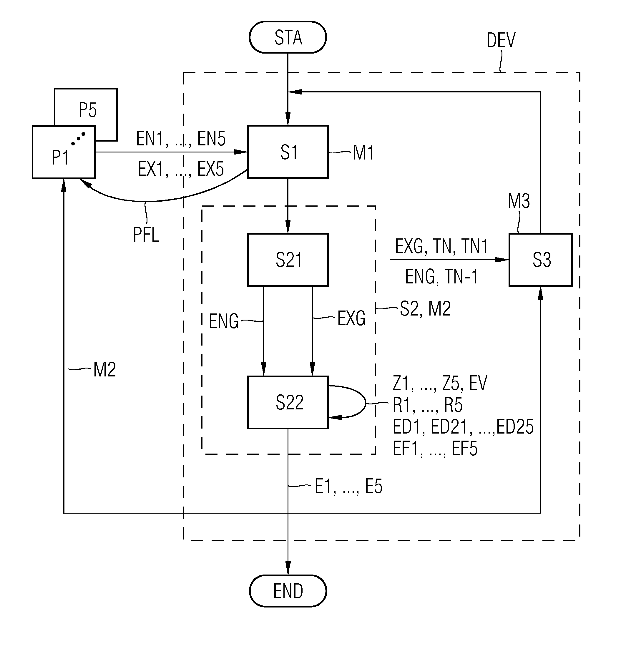
[0033]FIG. 1 shows a flowchart for carrying out one embodiment of a method for allocating amounts of energy.

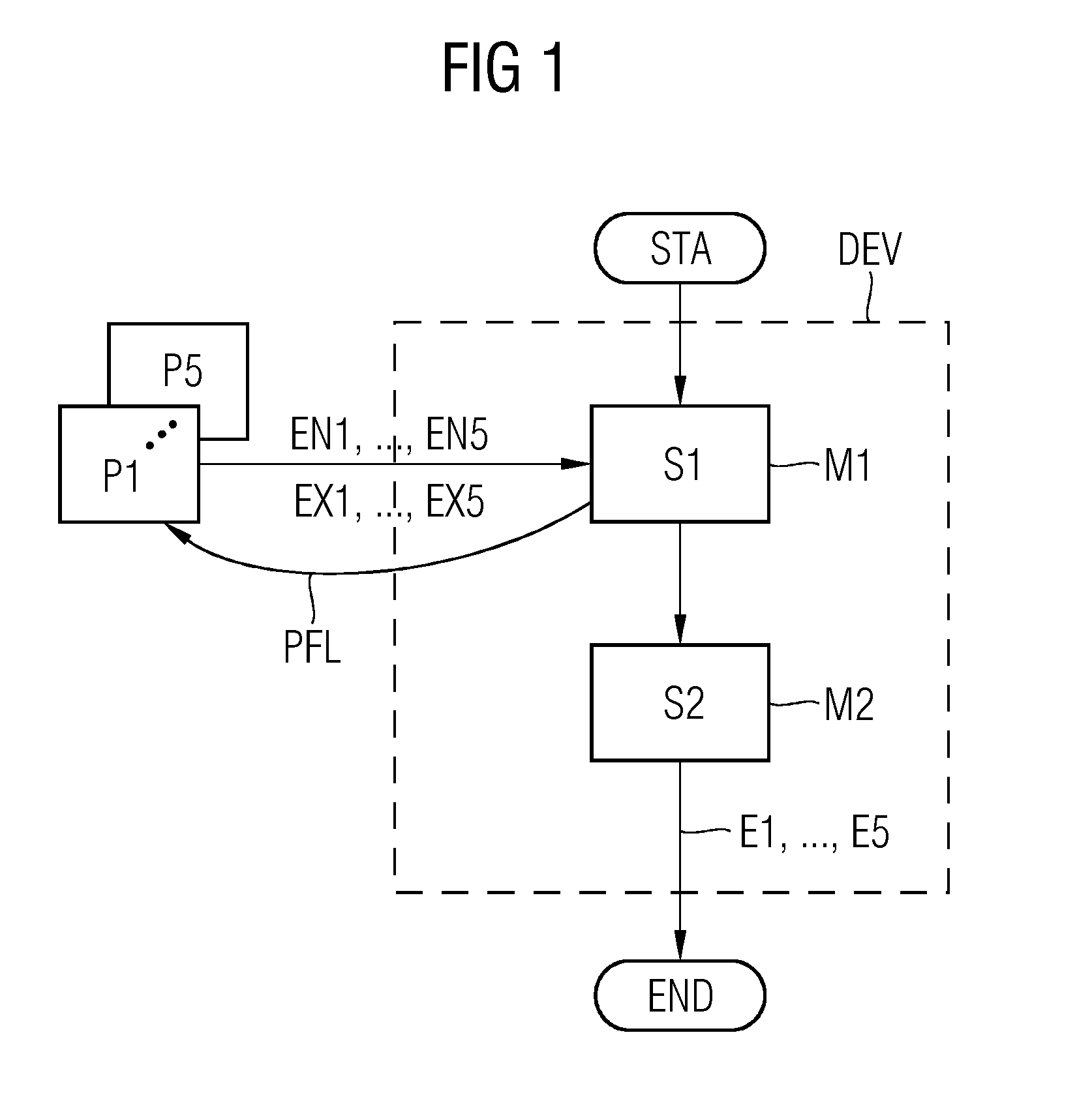
[0034]By way of example, in act S1, prosumers P1, . . . , P5 use a central unit to request respective minimum amounts of energy EN1, . . . , EN5 and maximum amounts of energy EX1, . . . , EX5 (see arrow PFL). The respective minimum and maximum amounts of energy per prosumer in an example are shown in FIG. 2.

[0035]In general, the maximum amount of energy defines an amount of energy that a prosumer may consume the most in a time interval or may minimally produce. In a way similar thereto, the minimum amount of energy defines an amount of energy that a prosumer may consume the least in a time interval or may maximally produce. Negative values of amounts of energy are available in FIG. 2 for providing amounts of energy, and positive values of amounts of energy ...


PUM


Abstract

The present invention relates to methods and apparatuses for allocating amounts of energy for prosumers, wherein the prosumers provide minimum and maximum amounts of energy for a future interval of time and the respective amounts of energy from the prosumers are generated in such a manner that, on the one hand, a relative position of the amount of energy within an interval for the particular prosumer, as defined by the minimum amount of energy and the maximum amount of energy, assumes an identical value for all prosumers and, on the other hand, a sum of the amounts of energy from all prosumers produces a value of zero. The invention can be used in the distribution of amounts of energy in a power supply system having conventional energy producers and energy consumers as well as in novel participants in the power supply system which can both consume and provide energy, for example an electric vehicle.

Description

[0001]The present application is a §371 nationalization of PCT Application No. PCT / EP2012 / 060141, filed May 30, 2012, and designating the United States, which, in turn, claims the benefit of DE 102011078045.9, filed on Jun. 24, 2011, the entire disclosures of which are incorporated by reference herein.BACKGROUND[0002]The present embodiments relate to methods and devices for allocating amounts of energy for prosumers in an electric grid.[0003]The progressive expansion of renewable energies is leading to an increasing decentralization of power generation. In addition, it is becoming increasingly more difficult to forecast an amount of energy to be expected or to be generated because of potentially larger fluctuations in energy in the case of renewable energies (e.g., because of weather dependence).[0004]This change may be taken into account by introducing smart electric grids that have in addition to the actual electric grid a communication network for exchanging information and for c...

Claims


Application Information

Patent Timeline
Patent Type & Authority Applications(United States)
IPC IPC(8): H02J4/00
CPCH02J4/00G06Q10/06G06Q50/06
Inventor GLOMB, CHRISTIANHEUER, JORGKUNTSCHKE, RICHARDWINTER, MARTIN
Owner SIEMENS AG
Why Eureka
Try Eureka