Power control device and power control method

a power control device and power control technology, applied in the direction of instruments, user interface execution, liquid/fluent solid measurement, etc., can solve the problems of low utilization rate of power in the integrated machine, limited use of thin client integrated machines, high price of switches, etc., and achieve the effect of total power consumption of the integrated machin

Active Publication Date: 2014-08-07
3M INNOVATIVE PROPERTIES CO
View PDF8 Cites 4 Cited by
  • Summary
  • Abstract
  • Description
  • Claims
  • Application Information

AI Technical Summary

Benefits of technology

[0002]In current computer networks, thin clients are becoming more and more important. According to the prediction of Gartner, an IT consulting organization, approximately 35% of desktops would be transformed to server computing-based or cloud computing-based thin clients by 2014. Currently, many organizations and companies, such as Lenovo and HP, are doing research on thin client products using network cables to supply power. At present, Power over Ethernet (POE) is a popular way to reduce the terminal costs, operation costs and installation costs of a thin client. IEEE 802.3 AT and IEEE 802.3 AF are two standards of using Power over Ethernet (POE) in which IEEE 802.3 AT provides a standard of supplying a power of 15.4 watts (W) by each network cable port, while IEEE 802.3 AF provides a standard of supplying four grade powers of 4 W, 7 W, 15.4 W and 30 W by each network cable port.
[0011]By using the power control device, the thin client, the integrated machine and the power control method as described above, the power consumption of the display can be adjusted so that the total power consumption of the integrated machine is kept stable thereby avoiding the low efficiency resulting from the power reservations for peripheral devices connected by a USB port.

Problems solved by technology

Such a high price of the switch has limited the use of the thin client integrated machines.
While the possibility of using such peripheral devices is low, the reservation of rated power for peripheral devices would result in a low utilization rate of the power in the integrated machine as described above.

Method used


Image

  • Power control device and power control method
  • Power control device and power control method
  • Power control device and power control method

Examples


Embodiment Construction

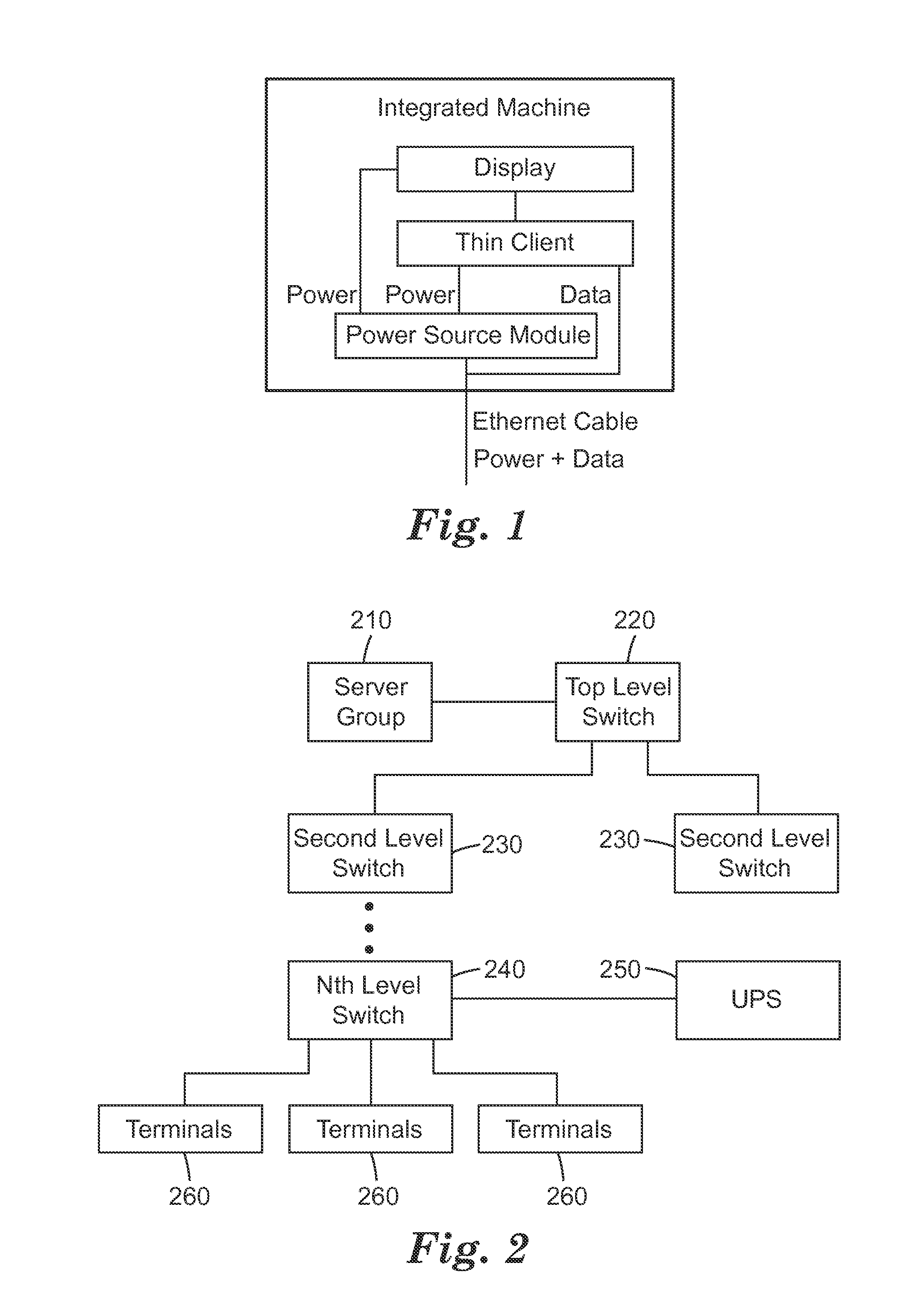
[0022]FIG. 2 is a diagram of a network structure using a thin client group. As shown in FIG. 2, the system comprises a server group 210, a top level switch 220 connected to the server group 210, a second level switch 230 connected to the top level switch, a bottom level switch 240 disposed at level N, terminals 260 preferably being a thin client integrated machine of the present invention, and a UPS 250 being a power source or a backup power source. In general, UPS 250 is disposed adjacent to the bottom level switch 240 such that terminals 260 are powered by UPS 250 via the bottom level switch 240. In actual applications, the network structure may only require one level of switch, i.e. the top level switch 220 is also the bottom level switch 240, and UPS 250 is connected to the top level switch 220. In some other cases, multi-level switches may be required. The present invention would not be limited to the network structure as illustrated.

[0023]As described above, the prior art uses...


PUM


Abstract

The present invention provides a power control device, a machine comprising the same and a power control method. The device is used for an integrated machine comprising a thin client and a display and comprises: a current detecting unit for detecting the current flowing through a port in the thin client connecting to the peripheral device; and a control signal generating unit for generating a control signal based on the intensity of the detected current to adjust the power consumption of the display and / or the thin client to maintain no increase in the power consumption of the integrated machine. The power control device, the machine comprising the same and the power control method of the present invention can be used to avoid low efficiency resulting from the power reservations for peripheral devices connected by a USB port.

Description

BACKGROUND[0001]The present invention relates to a power supply integrated machine. Specifically, the present invention relates to a power control device included in an integrated machine and a power control method.SUMMARY[0002]In current computer networks, thin clients are becoming more and more important. According to the prediction of Gartner, an IT consulting organization, approximately 35% of desktops would be transformed to server computing-based or cloud computing-based thin clients by 2014. Currently, many organizations and companies, such as Lenovo and HP, are doing research on thin client products using network cables to supply power. At present, Power over Ethernet (POE) is a popular way to reduce the terminal costs, operation costs and installation costs of a thin client. IEEE 802.3 AT and IEEE 802.3 AF are two standards of using Power over Ethernet (POE) in which IEEE 802.3 AT provides a standard of supplying a power of 15.4 watts (W) by each network cable port, while I...

Claims


Application Information

Patent Timeline
Patent Type & Authority Applications(United States)
IPC IPC(8): G06F1/32
CPCG06F1/3215G06F1/324G06F1/3265G06F9/452G06F13/00Y02D10/00G06F1/3206G06F1/266G06F1/3234G06F1/329G06F1/3296
Inventor DU, GUANGLEIKECMAN, FEDJASIEFKEN, SHANNON L.
Owner 3M INNOVATIVE PROPERTIES CO
Why Eureka
Try Eureka