
Extended-span and alternatively-shaped arch bridge and construction method therefor

a technology of arch bridge and extension span, which is applied in the field of large-span combination arch bridge, can solve the problems of large greater difficulty in controlling lateral stability, and higher construction difficulty, and achieves the reduction of the bending moment of the cross-section of the main arch at the central bearing point, the effect of significant bending strength of the cross-section of the arch bridge and the bending strength of the cross-section

Inactive Publication Date: 2014-08-14
SHENZHEN BRIDGE DESIGN & RES INST +1
View PDF8 Cites 8 Cited by
  • Summary
  • Abstract
  • Description
  • Claims
  • Application Information

AI Technical Summary

Benefits of technology

The present invention provides a special-shaped arch bridge that can reduce bending moments and deformation of the main girder using a dual-arch axis. This increases the bending strength of the arch and reduces the force on the entire bridge, resulting in a more reasonable construction cost and period.

Problems solved by technology

However, there are some defects in the existing large-span arch bridges with larger horizontal thrust, greater difficulty in controlling lateral stability as well as higher difficulty in construction.
1, due to the adjustment of the arch axis, the bending moment of the cross-section of main arch at the central bearing point is larger, and the material cost of the section of main arch is greater;
2, since the arch axis deviates from the pressure line of the arch, a greater bending moment and larger vertical displacement at the haunch of the arch are made, which leads to great deformation of main girder, therefore hardly meeting the functional requirements of normal working.

Method used


Image

  • Extended-span and alternatively-shaped arch bridge and construction method therefor
  • Extended-span and alternatively-shaped arch bridge and construction method therefor
  • Extended-span and alternatively-shaped arch bridge and construction method therefor

Examples


Embodiment Construction

[0038]Hereinafter is given embodiments accompanied with the drawings to describe the present invention in further details:

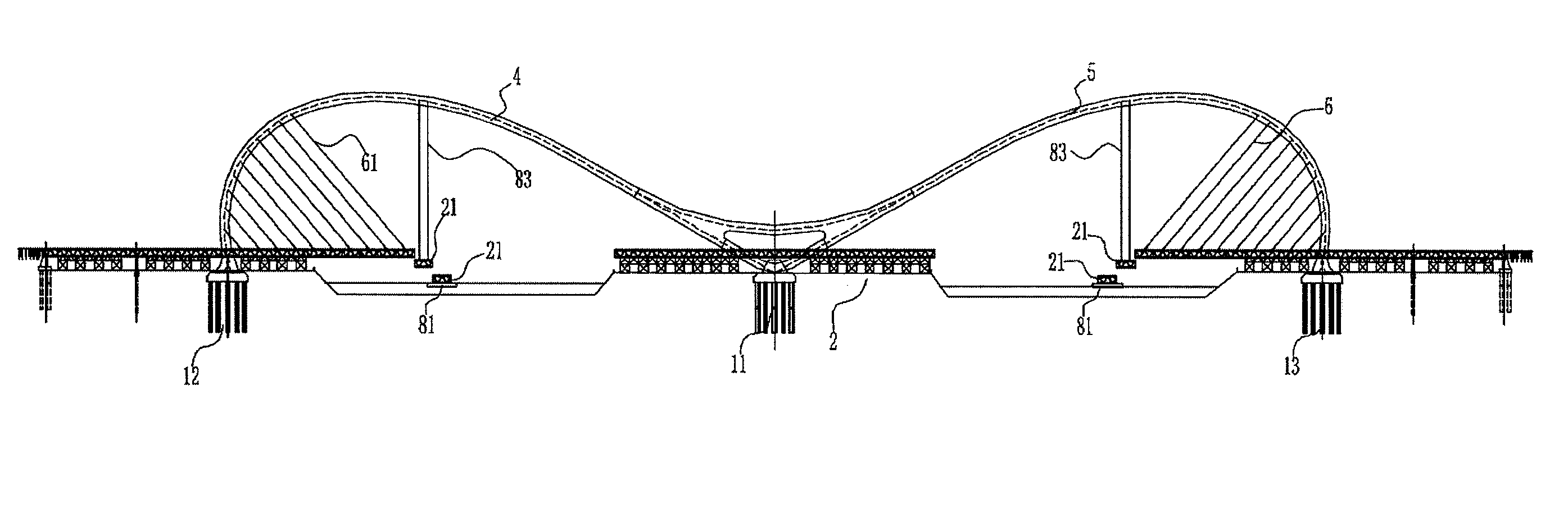
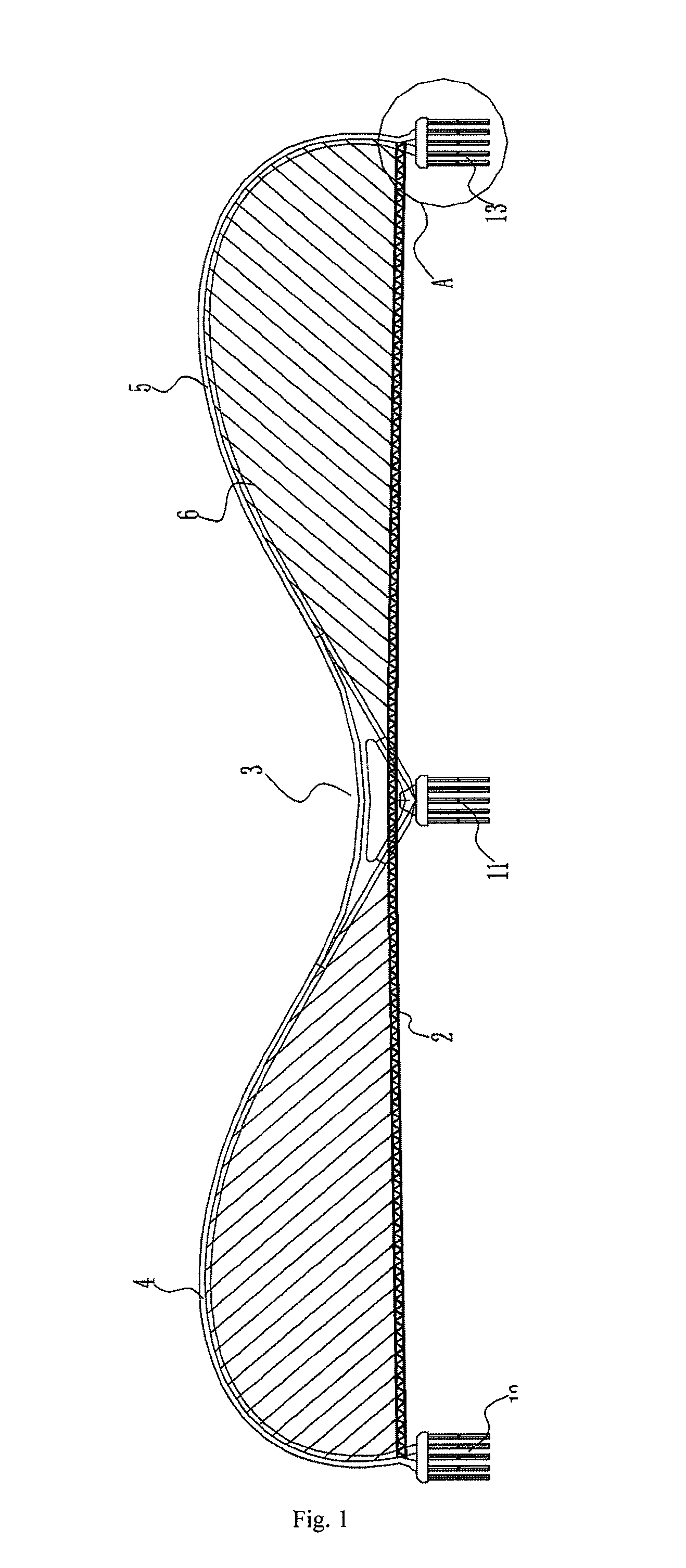
[0039]Referring to FIG. 1, a large-span and special-shaped arch bridge in accordance with an embodiment of the present invention is provided, which comprises a main girder 2, a center abutment 11 and two auxiliary abutments 12,13. The center abutment 11 is served as a central bearing point of the entire combination arch bridge, and the two auxiliary abutments 12, 13 as two bearing points at two ends of the bridge. An arch-axis combination 3 is fixed on the center abutment 11. The center abutment 11 connects to the two auxiliary abutments 12,13 with an arch-axis bending beam 4,5 respectively. The arch-axis bending beams 4,5, which are provided with an arch axis respectively, arranged symmetrically and each presented as an arc projected upwards, are respectively formed by a plurality of arch-axis bending beam segments butted in sequence.

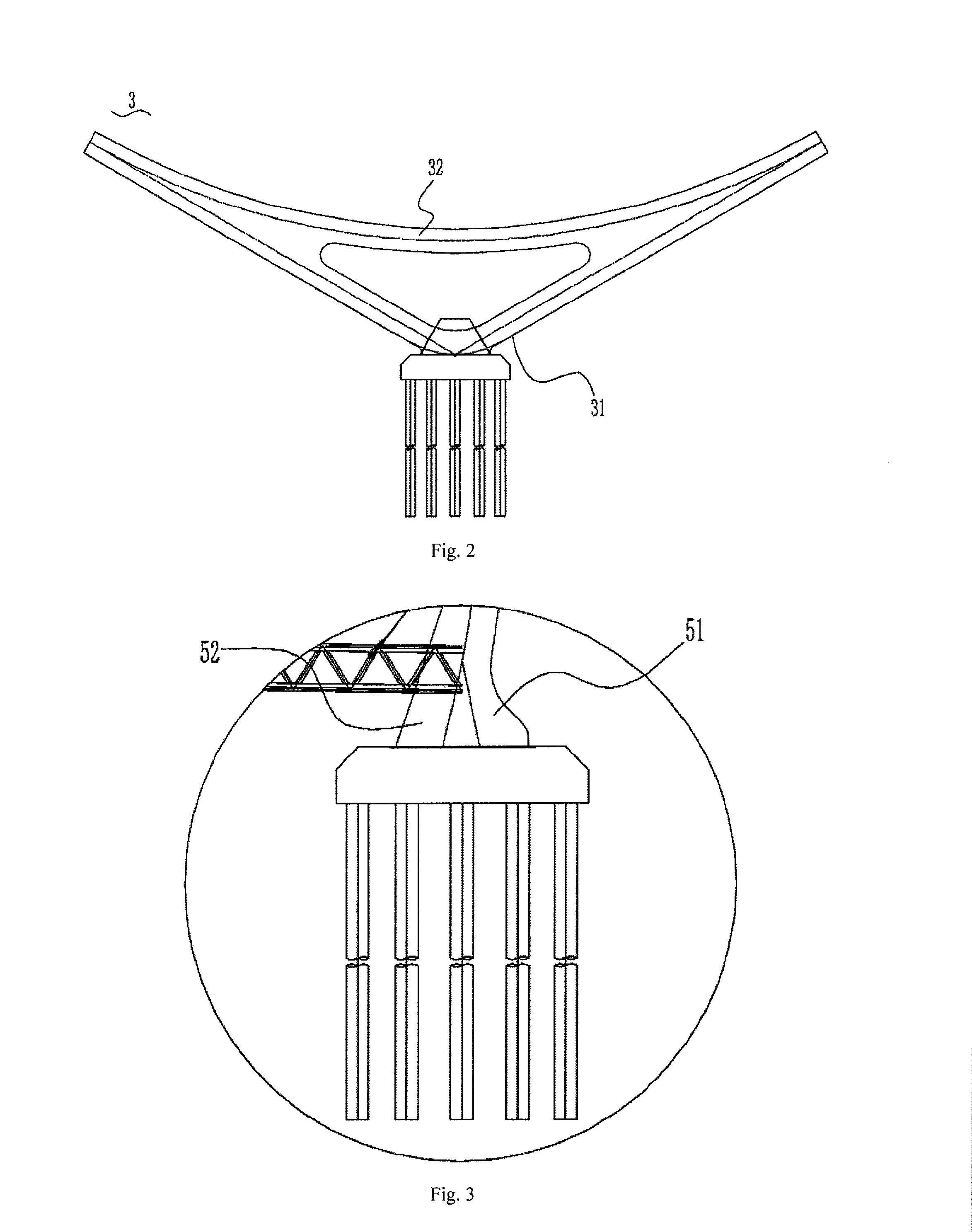
[0040]Referring to FIG. 2 an...


PUM


Abstract

A large-span and special-shaped arch bridge, comprising a main girder (2), a center abutment (11) served as a central bearing point and two auxiliary abutments (12,13) served as bearing points at two ends, wherein further comprising an arch-axis combination (3) and two arch-axis bending beams (4,5) presented as arcs projected upwards, the arch-axis combination being built on the center abutment (11) with two ends connected to the inner ends of the two arch-axis bending beams (4,5), the outer ends of the two arch-axis bending beams (4,5) being built on the two auxiliary abutments (12,13), the two arch-axis bending beams (4,5) being connected to the main girder (2) via a plurality of inhaul cables. A method for constructing said arch bridge is also disclosed. Through the dual-arch axis of two arch-axis bending beams, the bending strength of the cross-section of the arch bridge is significantly increased, the bending moment of the cross-section of the arch at the central bearing point is decreased, the vertical displacement at the haunch of the arch is lesser, and the deformation of the main girder is reduced, thus the force of the entire bridge is more reasonable, the construction cost can effectively be reduced and the construction period can be shortened.

Description

TECHNICAL FIELD[0001]The present invention relates to bridges, particularly to a large-span combination arch bridge and a method for construction thereof.PRIOR ART[0002]Owing to the advantages of large span, beautiful shape and making full use of compressive strength of materials, more designs of arch bridge have been used in existing construction of bridges. However, there are some defects in the existing large-span arch bridges with larger horizontal thrust, greater difficulty in controlling lateral stability as well as higher difficulty in construction.[0003]U.S. Pat. No. 7,469,438 discloses an arch axis which can effectively solve the above-mentioned defects and result in a reduced horizontal thrust of an arch bridge and a better lateral stability. However, it still has the following disadvantages:[0004]1, due to the adjustment of the arch axis, the bending moment of the cross-section of main arch at the central bearing point is larger, and the material cost of the section of ma...

Claims


Application Information

Patent Timeline
Patent Type & Authority Applications(United States)
IPC IPC(8): E01D4/00E01D21/00
CPCE01D21/00E01D4/00E01D6/02E01D12/00
Inventor LI, YONGCHEN, YIYANLI, MINGUO, SHUAIXIAO, FANGFANG
Owner SHENZHEN BRIDGE DESIGN & RES INST
Learn More