Eureka AIR delivers breakthrough ideas for toughest innovation challenges, trusted by R&D personnel around the world.

Method and device for mixing compressed air and reducing agent and motor vehicle having the device

Active Publication Date: 2014-08-14
EMITEC GESELLSCHAFT FUR EMISSIONSTECHNOLOGIE MBH +1
View PDF5 Cites 5 Cited by
  • Summary
  • Abstract
  • Description
  • Claims
  • Application Information

AI Technical Summary

Benefits of technology

The patent describes a method for mixing reducing agents and compressed air in a controlled and efficient way. The compressed air is injected into the reducing agent flow through a narrowed duct, which allows for acceleration of the air and ensures fine atomization of the reducing agent. The method also includes the use of a continuous conversion process, where the compressed air is gradually depleted and the reducing agent flow is expanded. This results in a more efficient mixing of the two flows, achieving improved mixing efficiency.

Problems solved by technology

In particular, the pressure of the reducing agent may fluctuate intensely during the operation of the device.

Method used


Image

  • Method and device for mixing compressed air and reducing agent and motor vehicle having the device
  • Method and device for mixing compressed air and reducing agent and motor vehicle having the device
  • Method and device for mixing compressed air and reducing agent and motor vehicle having the device

Examples


Embodiment Construction

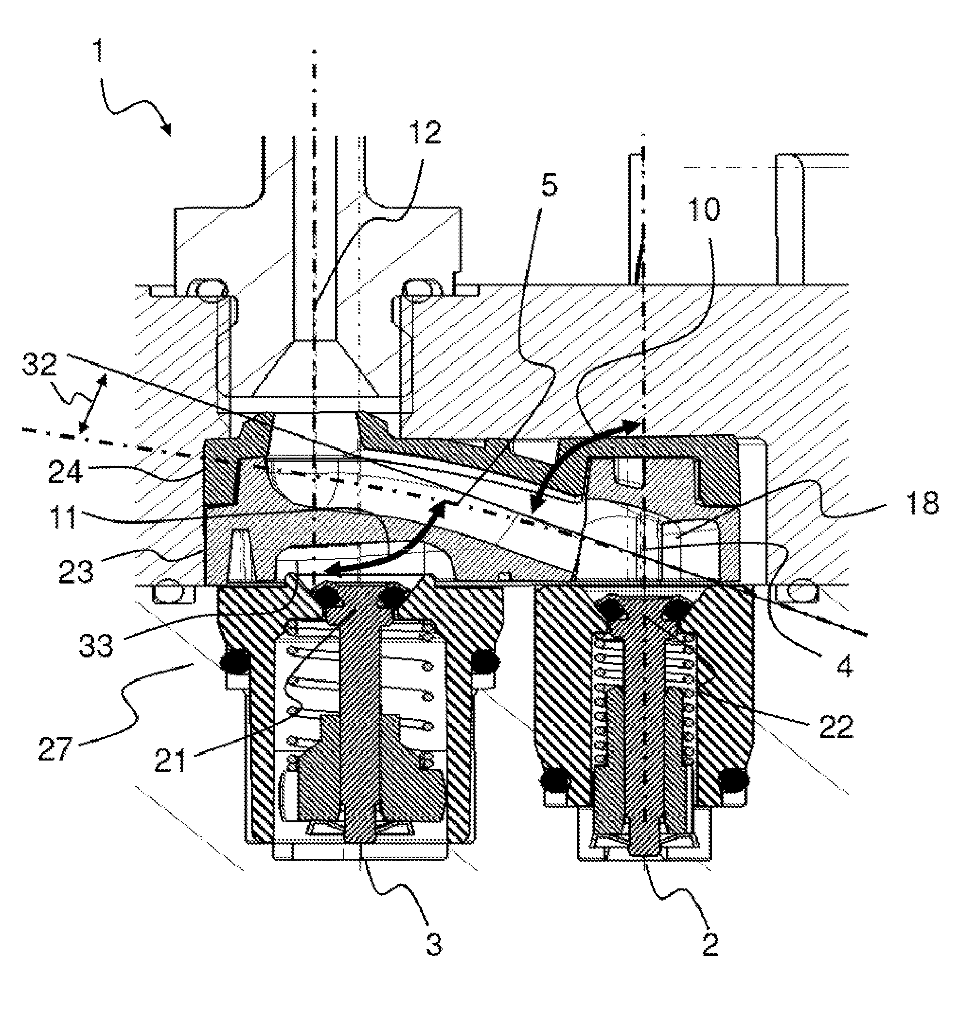
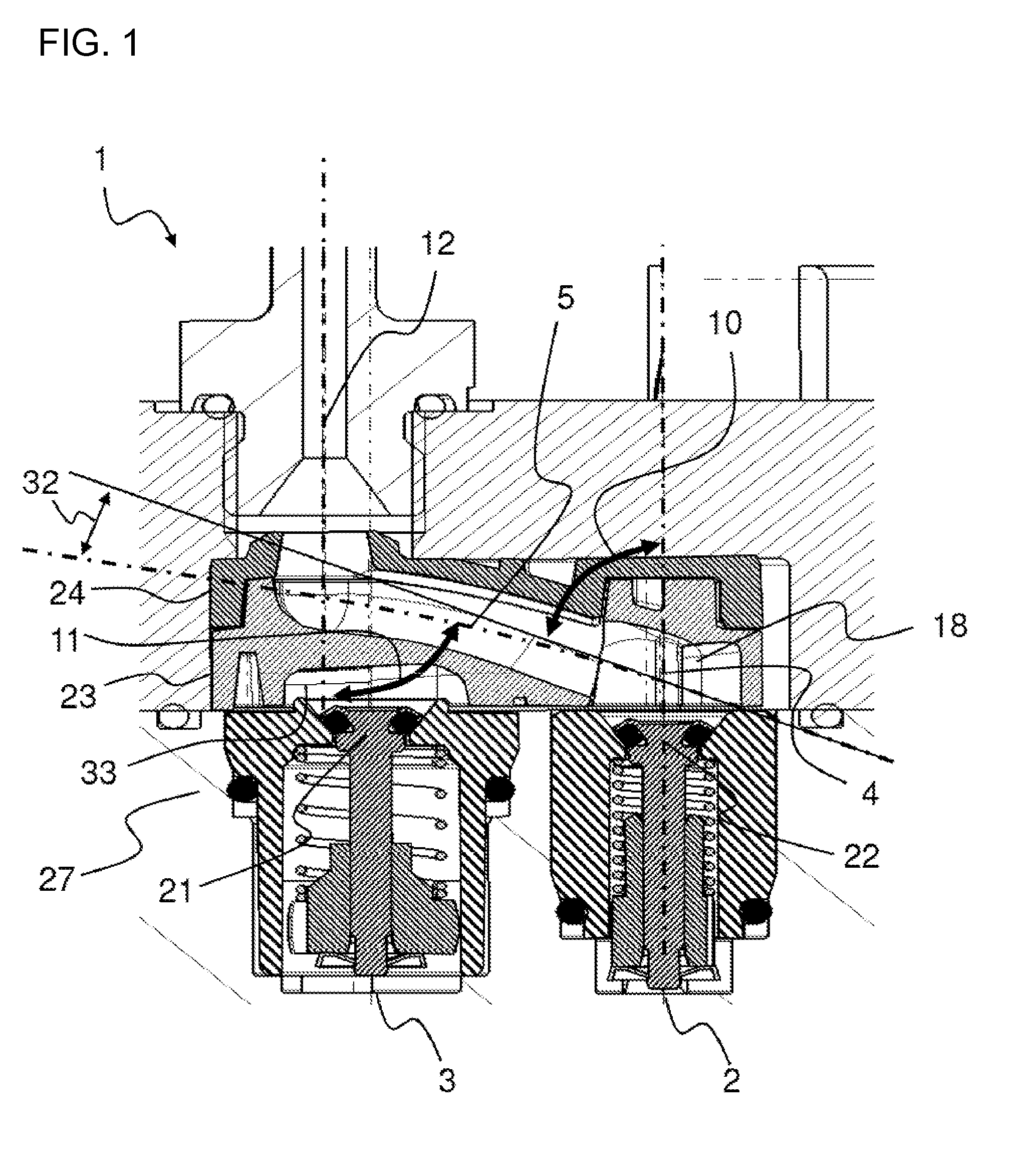
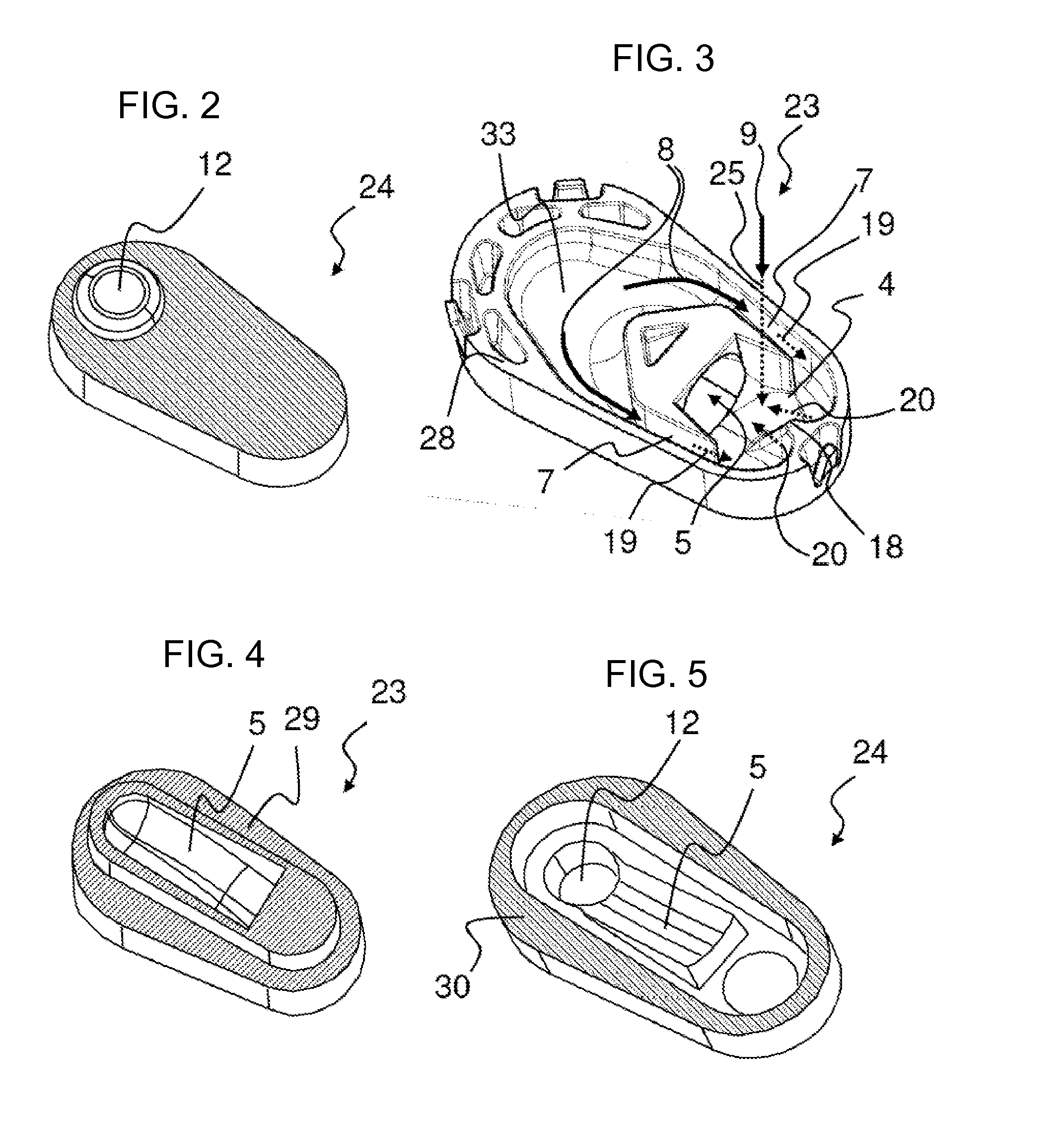
[0057]Referring now in detail to the figures of the drawings, which show particularly preferred exemplary embodiments to which the invention is not restricted and in which proportions are merely diagrammatic, and first, particularly, to FIG. 1 thereof, there is seen a section through a device 1 according to the invention. The device 1 is composed of a lower first component 23 and of an upper second component 24, which together can be mounted on a base plate 27. The base plate 27 may, for example, be a constituent part of a pump module which serves for delivering the reducing agent and / or for delivering the air. Reducing agent passes through a first inflow duct 2 into the device 1. Air passes through a second inflow duct 3 into the device 1. The supply of reducing agent can be regulated by using a first valve 22 in the first inflow duct 2. The supply of air can be regulated by using a second valve 21 in the second inflow duct 3. The first inflow duct 2 opens into a mixing point 4 in ...


PUM


Abstract

A device for providing a mixture of compressed air and liquid reducing agent includes a first inflow duct for reducing agent, a second inflow duct for compressed air, an outlet duct for the mixture, a mixing point at which compressed air and reducing agent are merged, and a mixing duct which adjoins the mixing point and which connects the mixing point and the outlet duct. The first inflow duct opens into the mixing point in an axial direction. The second inflow duct is connected to the mixing point through at least one injection duct. The at least one injection duct opens into the mixing point in a tangential direction. A method for mixing liquid reducing agent and compressed air to form a mixture and a motor vehicle having the device, are also provided.

Description

CROSS-REFERENCE TO RELATED APPLICATION[0001]This is a continuation, under 35 U.S.C. §120, of copending International Application No. PCT / EP2012 / 069376, filed Oct. 1, 2012, which designated the United States; this application also claims the priority, under 35 U.S.C. §119, of German Patent Application DE 10 2011 116 336.4, filed Oct. 19, 2011; the prior applications are herewith incorporated by reference in their entirety.BACKGROUND OF THE INVENTIONField of the Invention[0002]The present invention relates to a method and a device for mixing compressed air and reducing agent and a motor vehicle having the device.[0003]In particular in the automotive field, for the purification of the exhaust gases of internal combustion engines, exhaust-gas treatment processes are used in which a fluid is added to the exhaust gas which assists in the conversion of pollutants in the exhaust gas. A particularly commonly used exhaust-gas treatment process in which a fluid is supplied is the selective cat...

Claims


Application Information

Patent Timeline
IPC IPC(8): B01F15/02F01N3/10
CPCF01N3/10B01F15/0227F01N3/2066F01N2610/02F01N2610/08Y02A50/20Y02T10/12F01N3/20F01N3/36B01F35/717
Inventor MARTINELLE, GUILLAUMEMERTES, PHILIPPEMAGUIN, GEORGES
Owner EMITEC GESELLSCHAFT FUR EMISSIONSTECHNOLOGIE MBH
Why Eureka
Eureka Blog
Learn More