Vectored-thrust propulsor

a propulsor and thrust vector technology, applied in the field of propellers, can solve the problems of inability of the pressure unit in the engine (compressor, combustion chamber) to provide for the reversible control of gas flow, the pegasus design fails to provide for the spatial control of the thrust vector and thrust moment in the full solid angle range, etc., to achieve the effect of improving maneuverability and effectiveness

Active Publication Date: 2014-08-14
IVANOV VLADIMIR E MR +1
View PDF1 Cites 3 Cited by
  • Summary
  • Abstract
  • Description
  • Claims
  • Application Information

AI Technical Summary

Benefits of technology

[0008]The object of the technical solution in the present disclosure is to provide an effective propulsor with sufficiently rapidly varying control and capable of creating both a thrust and a thrust moment (turn force), a vector of the thrust and a vector of the thrust moment being each value controlled, the direction of each of those vectors being controlled in a maximum wide angle range up to a full solid angle, no matter what the propulsor spatial orientation is. Thus, a propulsor providing enhanced maneuverability and effectiveness when moving in a three-dimensional gaseous or liquid medium can be realized.

Problems solved by technology

However, no prior art propulsors have been known to provide for effective spatial control of the thrust vector and moment in a full solid angle range.
However, pressure units in those engines (compressors, combustion chambers) fail to provide for the gas flow reversible control.
Additionally, the Pegasus design fails to provide for the spatial control of the thrust vector and thrust moment in the full solid angle range.
The prior art system, however, does not comprise duct reversal pressure units, which would be important to make the system work effectively as a propulsor rather than a control system.

Method used


Image

  • Vectored-thrust propulsor
  • Vectored-thrust propulsor
  • Vectored-thrust propulsor

Examples


Embodiment Construction

[0017]The following terms have been used throughout the description:

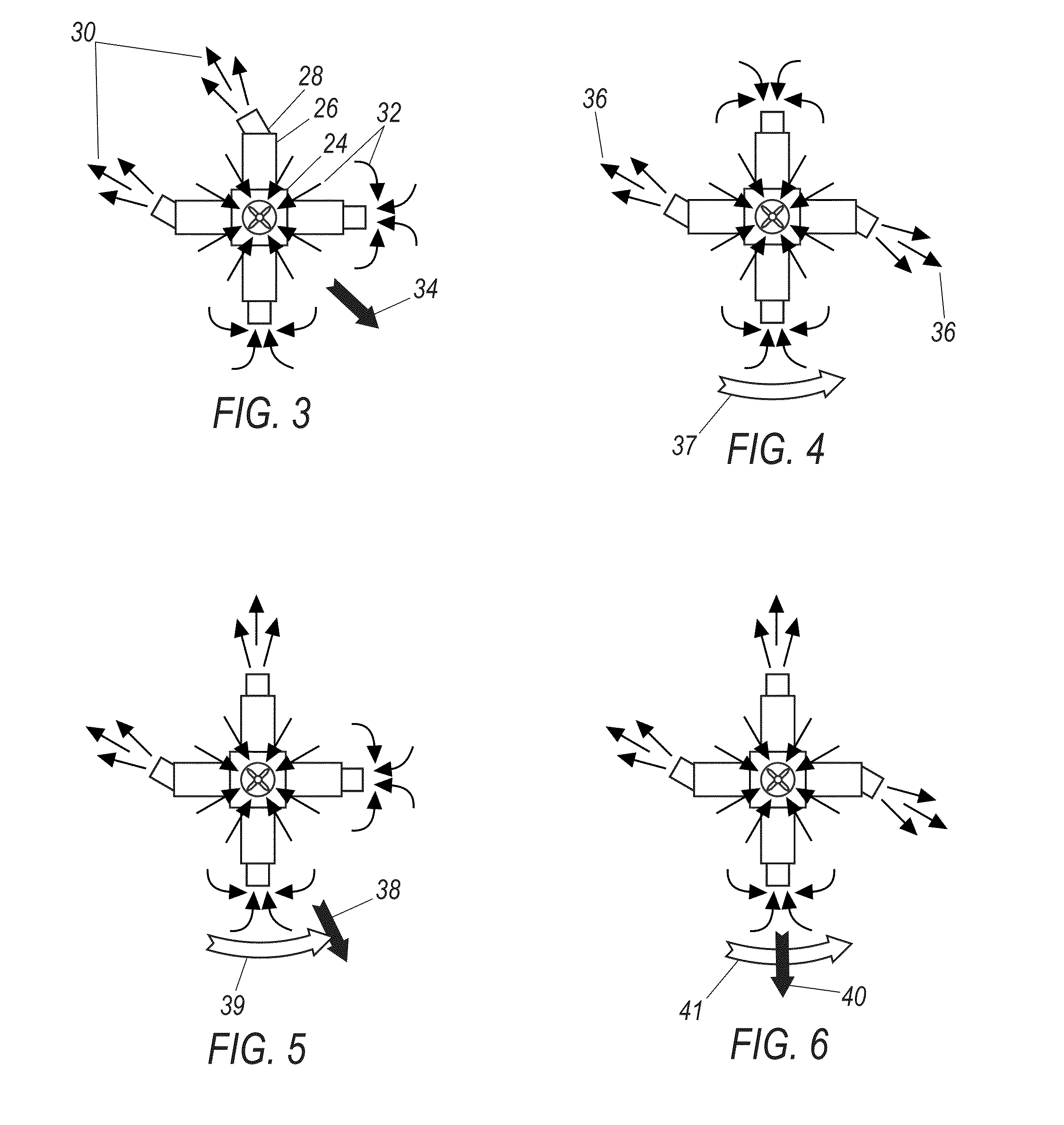
[0018]“Working fluid”—that portion of ambient gas or liquid which is accommodated within propulsor internal space; a jet force emerging upon ejecting the working fluid from the propulsor into outside environment is used for creating thrust and thrust moment.

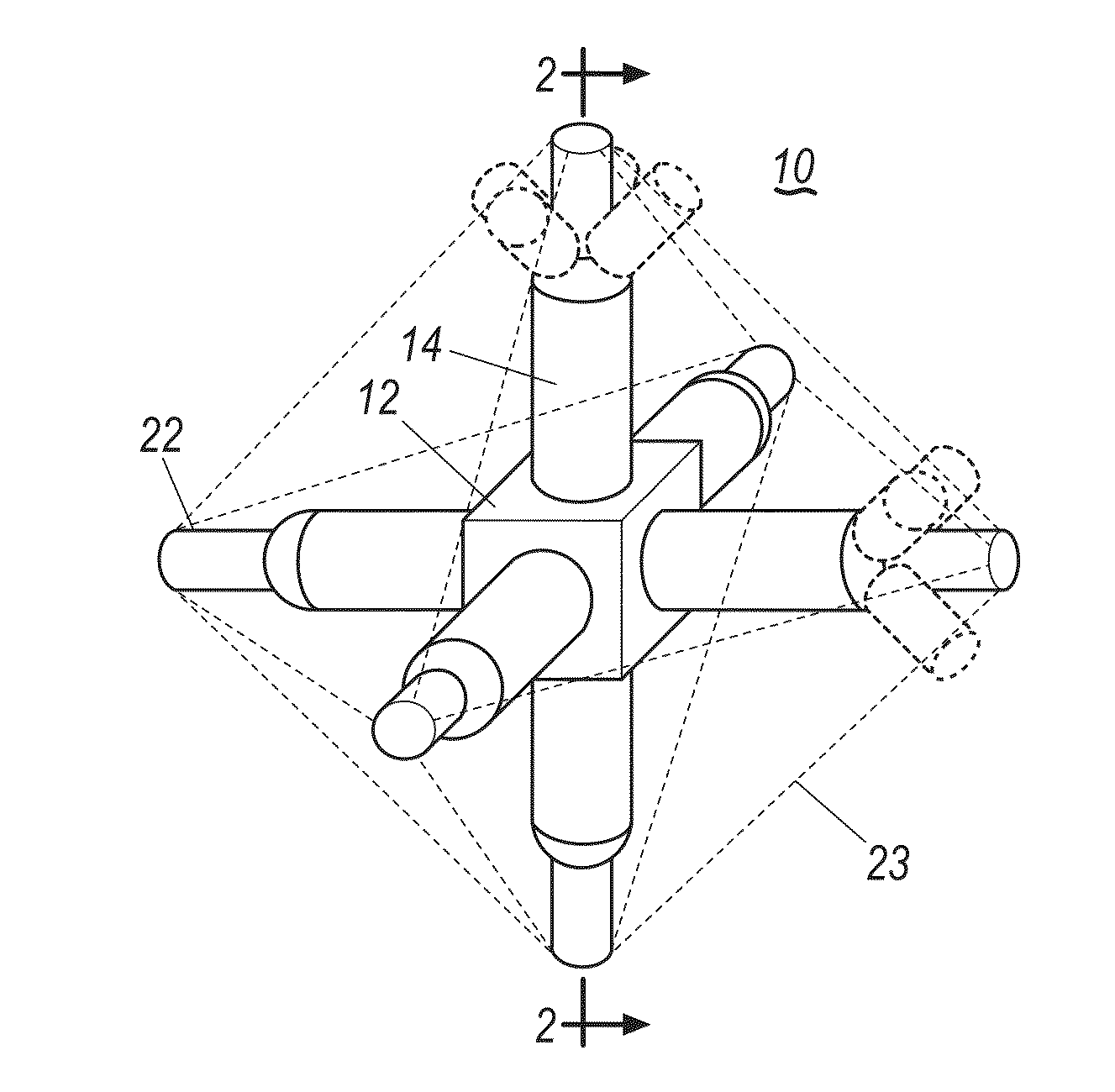
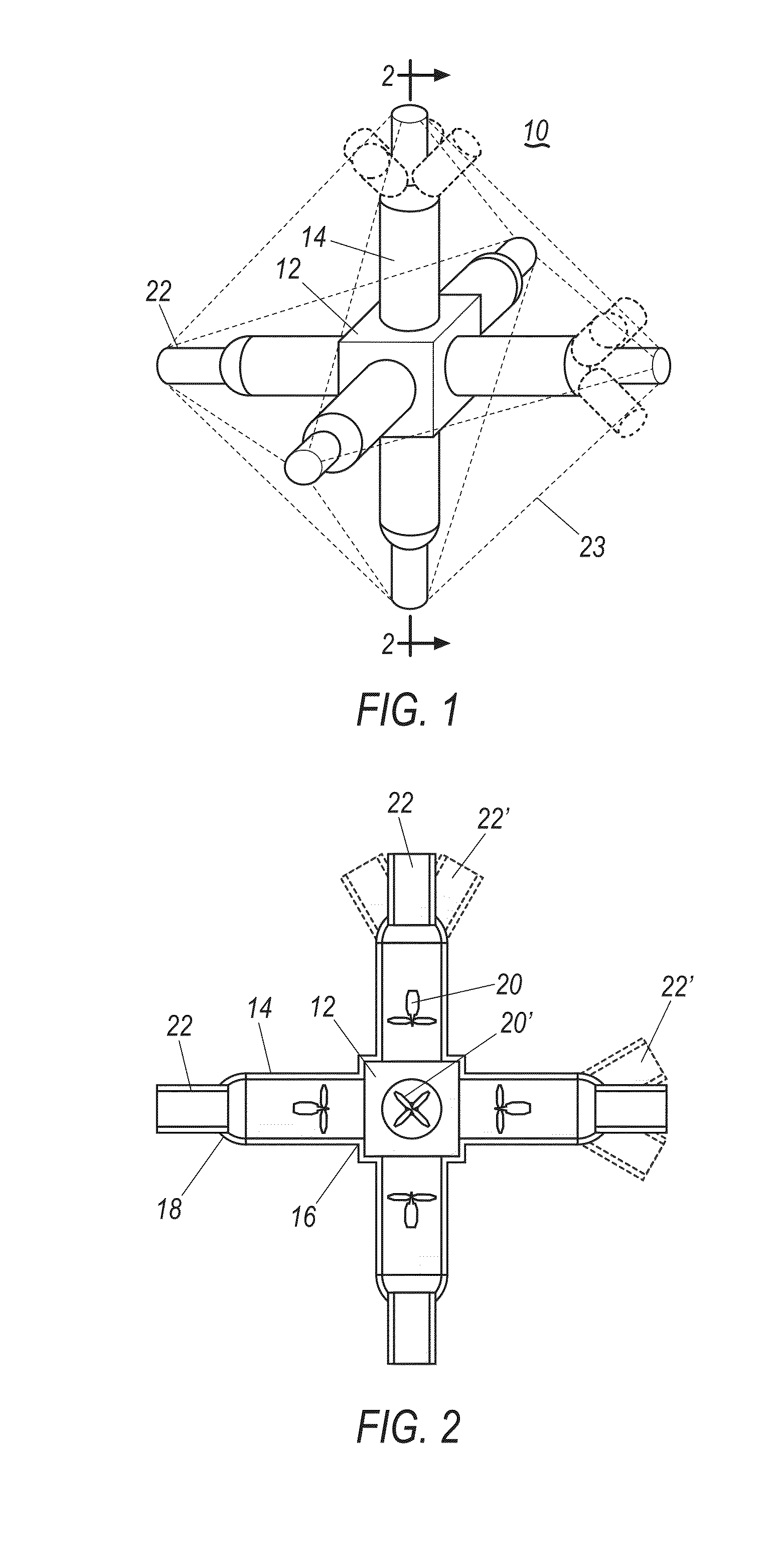
[0019]“Joint (flow) chamber”—an enclosed volume, which all passaged are connected to with one end thereof; the passages are open into the chamber; technically, the chamber can include no proper, clearly expressed structural elements, but rather present a propulsor common internal space where the passages interconnect (intersect); accordingly, to be understood by “joint chamber” in this application is the above-mentioned common space at the place of the interconnection of the passages.

[0020]“Flow passage”—a structural volume designed for the working fluid movement within same outwardly from the joint chamber and inwardly from outside toward the joint chamber; ther...


PUM


Abstract

A jet propulsor, for use in vehicles or other devices moving in a three-dimensional gaseous or liquid medium such as air or water, has a joint chamber and at least four flow passages which are connected to the chamber with one of their ends, have independently controllable reversible pressure units inside, and are provided with independently controllable nozzles on their other ends. The propulsor pumps gas or liquid from the environment through itself and, because of reaction forces, provides for simultaneously and independently controlled thrust and thrust moment in terms of their value/strength and direction. Spatial control of the thrust vectoring and conditional thrust moment vector can be provided for in the spatial range of a full solid angle.

Description

CROSS-REFERENCE TO RELATED APPLICATIONS[0001]This application is a U.S. National phase continuation-in-part application of the International application PCT / RU2011 / 000347, filed May 20, 2011 claiming priority to Russian application 2010123344, filed Jun. 8, 2010, the entire content of the International and Russian applications being hereby incorporated in their entirety into the present application by reference.BACKGROUND OF THE DISCLOSURE[0002]1. Field of Technology[0003]The present disclosure relates to propulsors and represents an apparatus for generating controllable thrust and thus for moving a vehicle or another object in a three-dimensional liquid (such as water) or gaseous (such as air) medium.[0004]2. Description of Related Art[0005]Similar apparatus well known in the art are, for example, hydro jet propulsors of various designs and configurations (see, for example, Kulikov C. V., Khramkin M. F. Hydro jet propulsors, the theory and design. L. Sudostroyeniye, 1980). Such pro...

Claims


Application Information

Patent Timeline
Patent Type & Authority Applications(United States)
IPC IPC(8): F02K9/60
CPCB63H11/10F02K9/60F02K9/80F02K9/88
Inventor IVANOV, VLADIMIR E.
Owner IVANOV VLADIMIR E MR
Why Eureka
Try Eureka