Printer and blade withdrawal mechanism thereof

Active Publication Date: 2014-08-14
SHENZHEN ZHENGTONG ELECTRONICS
View PDF2 Cites 4 Cited by
  • Summary
  • Abstract
  • Description
  • Claims
  • Application Information

AI Technical Summary

Benefits of technology

[0004]The invention is intended to solve the technical issues by means of avoiding the deficiencies of the above the prior art, and put forward

Problems solved by technology

However, such structure wastes time and energy at handli

Method used


Image

  • Printer and blade withdrawal mechanism thereof
  • Printer and blade withdrawal mechanism thereof
  • Printer and blade withdrawal mechanism thereof

Examples


Embodiment Construction

[0032]To further illustrate the principle and structure of the invention, the invention is further described in detail in accordance with the preferable embodiments shown in the figures.

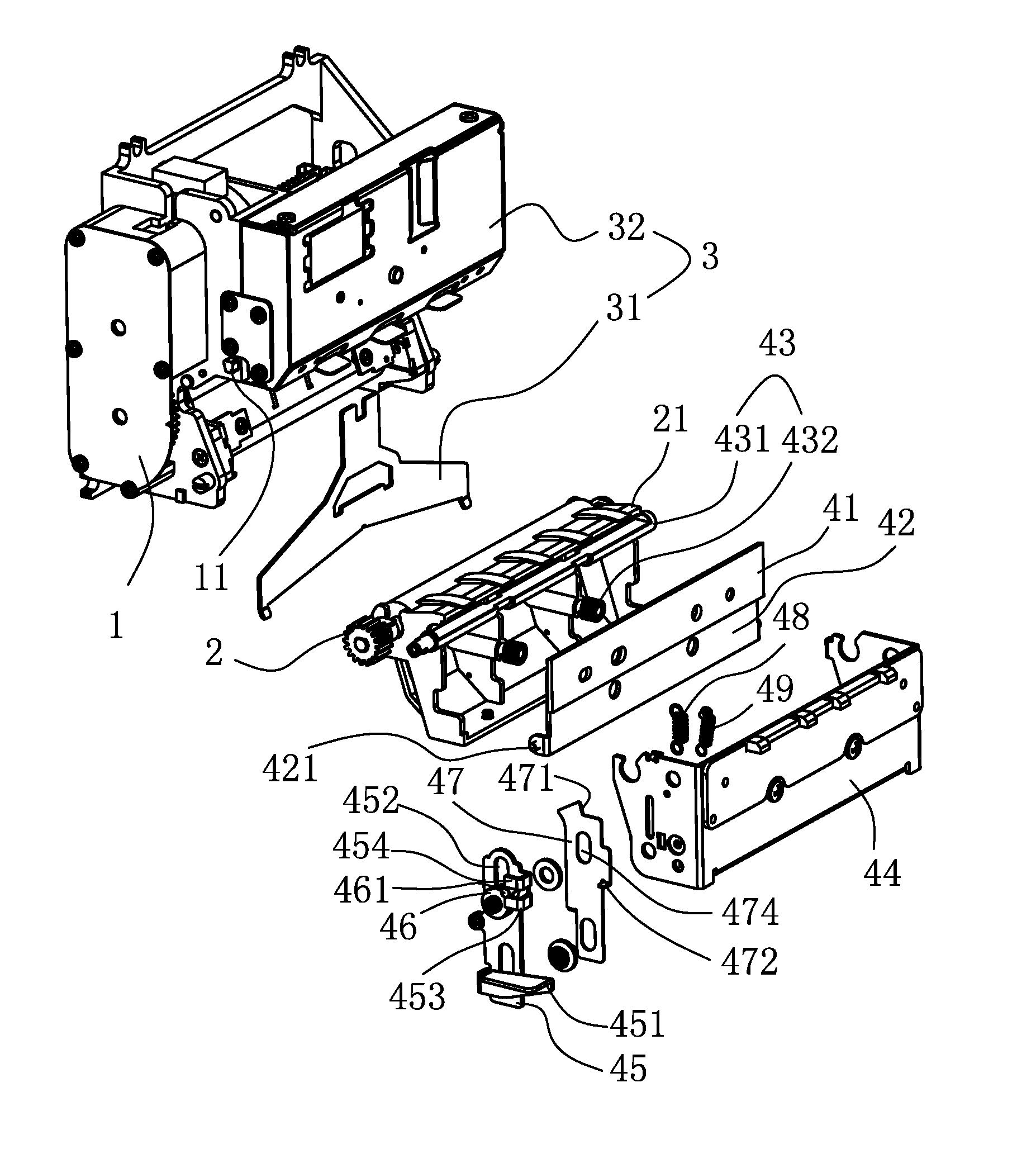
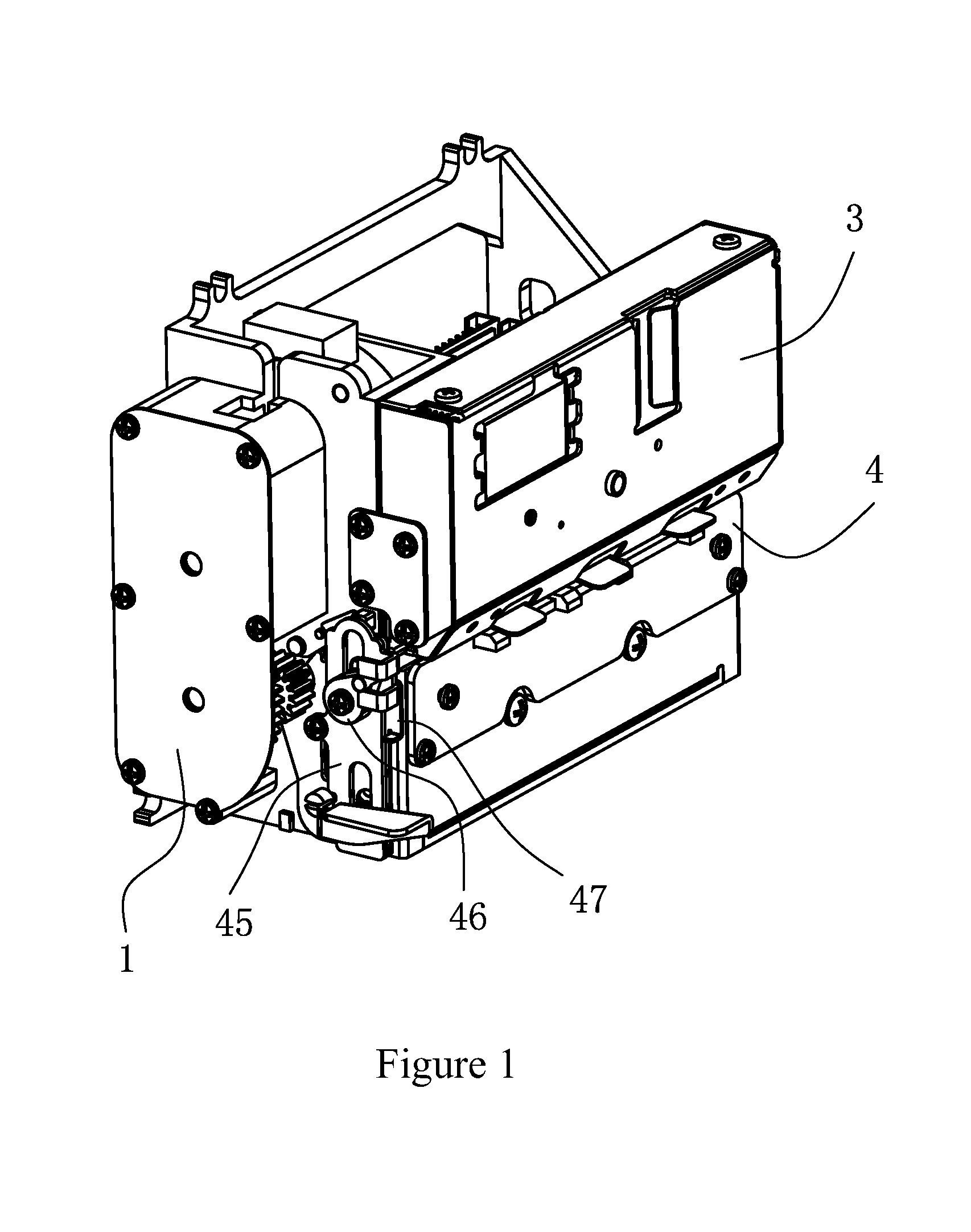
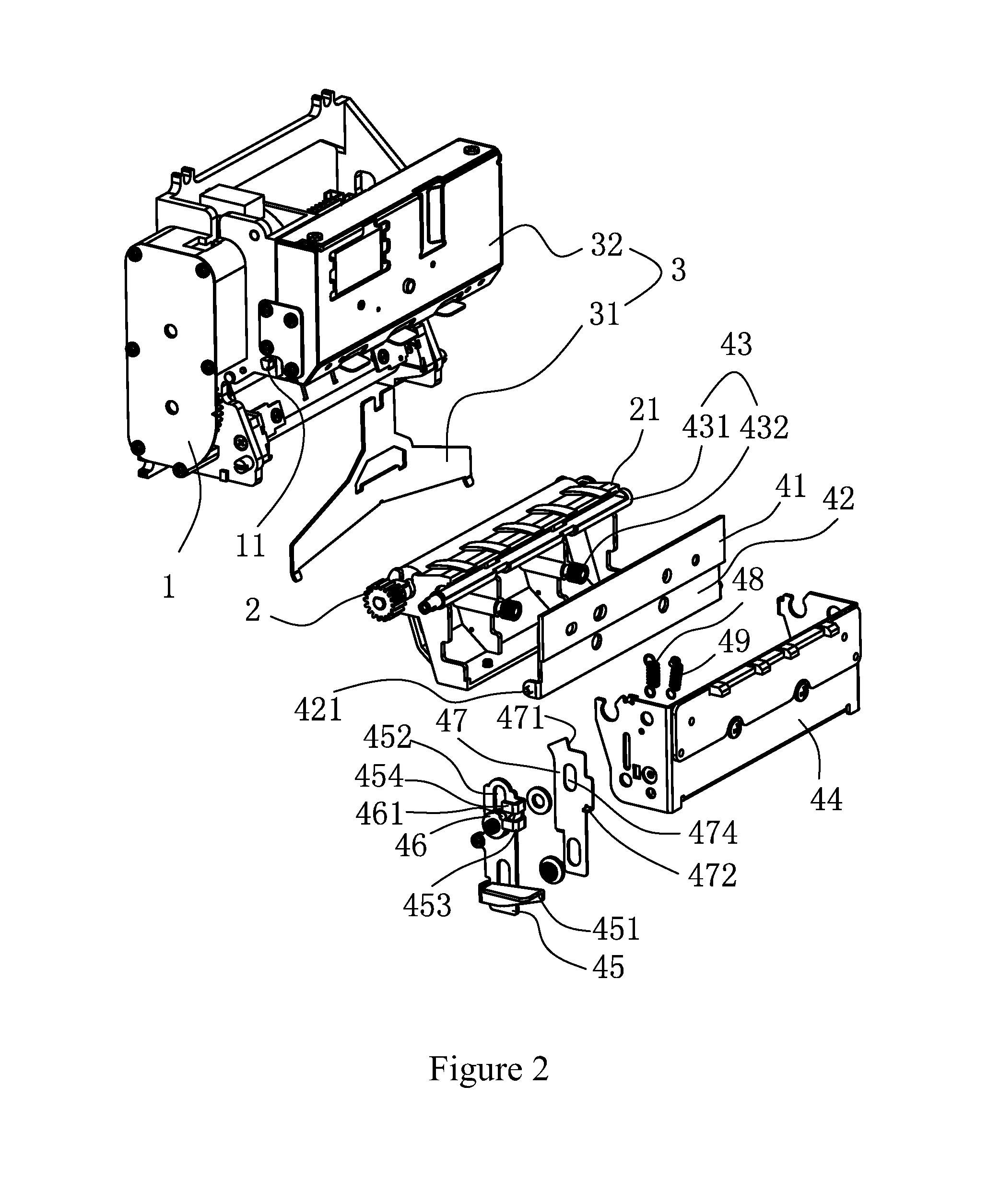
[0033]See FIG. 1, FIG. 2 and FIG. 3, printer embodiment of the invention roughly comprises: main body 1, top-cut blade part 3 and down-cut blade part 4.

[0034]The top-cut blade part 3 comprises the top-cut blade 31 and the drive unit 32. See FIG. 5, the drive unit is composed of motor 321, dial wheel 322, worm 323 and cam mechanism 324. The dial wheel 322 is connected with the worm 323 as a whole, worm 323 can be driven by the dial wheel 322 while the latter is poked artificially, thus enabling the cam mechanism 324 to drive the top-cut blade 31 installed thereupon to move up and down.

[0035]The down-cut blade part 4 comprises the down-cut blade 41, the paper cutting unit 2, the installing support 44 and the blade withdrawal mechanism In the embodiment, the installing support 44 is the plate sealing co...


PUM

PropertyMeasurementUnit
Angleaaaaaaaaaa
Flexibilityaaaaaaaaaa
Efficiencyaaaaaaaaaa

Abstract

A printer and its blade withdrawal mechanism, comprising: a fixing board, used for fixing a down cutter, the lower end of the fixing board can be pivotally installed on an installing support, and lower end of the installing support can be pivotally installed on a main body; a balance unit, which is installed on the installing support, and can act on the combination of the fixing board and the down-cut blade from front and rear, so as to enable the combination to be at non-pivotal state or at blade withdrawal state of pivoting by certain angle backward; a locking unit, for enabling the installing support to be at the locking state of being connected to the main body non-pivotally or at the open state of pivoting by certain angle forward; and a manipulation unit, which is installed on the installing support, located at one side of the combination of the fixing board and the down-cut blade, and can move downward by two segment travels under the effect of external force, at the first segment travel, it can act on the balance unit, while at the second segment travel, it can act on the locking unit. The invention can simplify the handling of the faults such as paper jam, and improve the handling efficiency.

Description

CROSS-REFERENCE TO RELATED APPLICATION[0001]This Application is a Section 371 National Stage Application of International Application No. PCT / CN2012 / 073269, filed Mar. 29, 2012 and published as WO 2013 / 040882 on Mar. 28, 2013, not in English, the contents of which are hereby incorporated by reference in their entirety.TECHNICAL FIELD[0002]The invention relates to a printer, especially blade withdrawal mechanism of the printer.BACKGROUND ART[0003]The printers of the prior art are generally installed with automatic cutting paper device, which generally consists of the mutually cooperated top-cut blade part and down cut-blade blade part, thereof, the top cut-cut blade part further comprises the top-cut blade which can move up and down, and the drive unit comprising motor, worm and cam mechanism. While the down-cut blade part comprises the fixed installed down-cut blade, paper cutting unit and installing support, where both the down-cut blade and the paper cutting unit are installed on ...

Claims


Application Information

Patent Timeline
IPC IPC(8): B41J11/70
CPCB41J11/706B26D7/00B26D7/22B26D1/085B26D7/2614B26D2007/005Y10T83/9488
Inventor JIANG, DUOYONG
Owner SHENZHEN ZHENGTONG ELECTRONICS
Why Eureka
Try Eureka