Helical graft

a helical graft and stent technology, applied in the field of grafts, can solve the problems of increased flow resistance, increased flow resistance, and inability to reliably induce swirl flow across the entire cross-section of flow

Active Publication Date: 2014-08-14
VERYAN MEDICAL LTD
View PDF14 Cites 0 Cited by
  • Summary
  • Abstract
  • Description
  • Claims
  • Application Information

AI Technical Summary

Benefits of technology

[0016]The graft according to the invention improves flow characteristics. As is well known, in the case of straight, tubes, near wall velocities are very low compared to velocities at the core of the tube, due to the effects of viscosity. In the case of tubes which are bent in a single plane, the speed of the flow at the outside of the bend is increased but the speed of the flow at the inside is retarded further. In both cases, there is considerable variation in axial velocity across the width of the tube. With the use of a helical tubing portion according to the invention, a swirl flow is generated and the axial velocity profile of the flow across the tubing portion becomes generally more uniform or “blunter”, with the axial velocity of flow at both the outside and inside of the tubing portion being closer to the mean axial velocity.
[0075]It is preferred in the above method to cause the tubular wall to retain, at least partly, the shape with the longitudinally extending helical cavity. This may be achieved for example by thermosetting.

Problems solved by technology

In cases where this swept width is relatively wide compared to the width of the tubing itself, the prosthesis or stent may be more bulky than is necessary or acceptable to induce the required swirl flow.
However, the use of ribs or grooves in an otherwise cylindrical tube may not reliably induce swirl flow across the entire cross-section of flow.
This may lead to increased flow resistance and a consequent pressure loss, and damage to blood vessels and blood cells and the development of pathology.
Again, however, a departure from circularity increases the ratio of the wetted perimeter to the cross-sectional area and will have disadvantages.
This proposal would therefore be relatively bulky and unsuitable for certain applications.
In fact, it is likely that the corrugations would tend to cause the flow to undergo sharp changes of direction leading to flow separation and the creation of stagnant near-wall regions.

Method used


Image

  • Helical graft
  • Helical graft
  • Helical graft

Examples


example 1

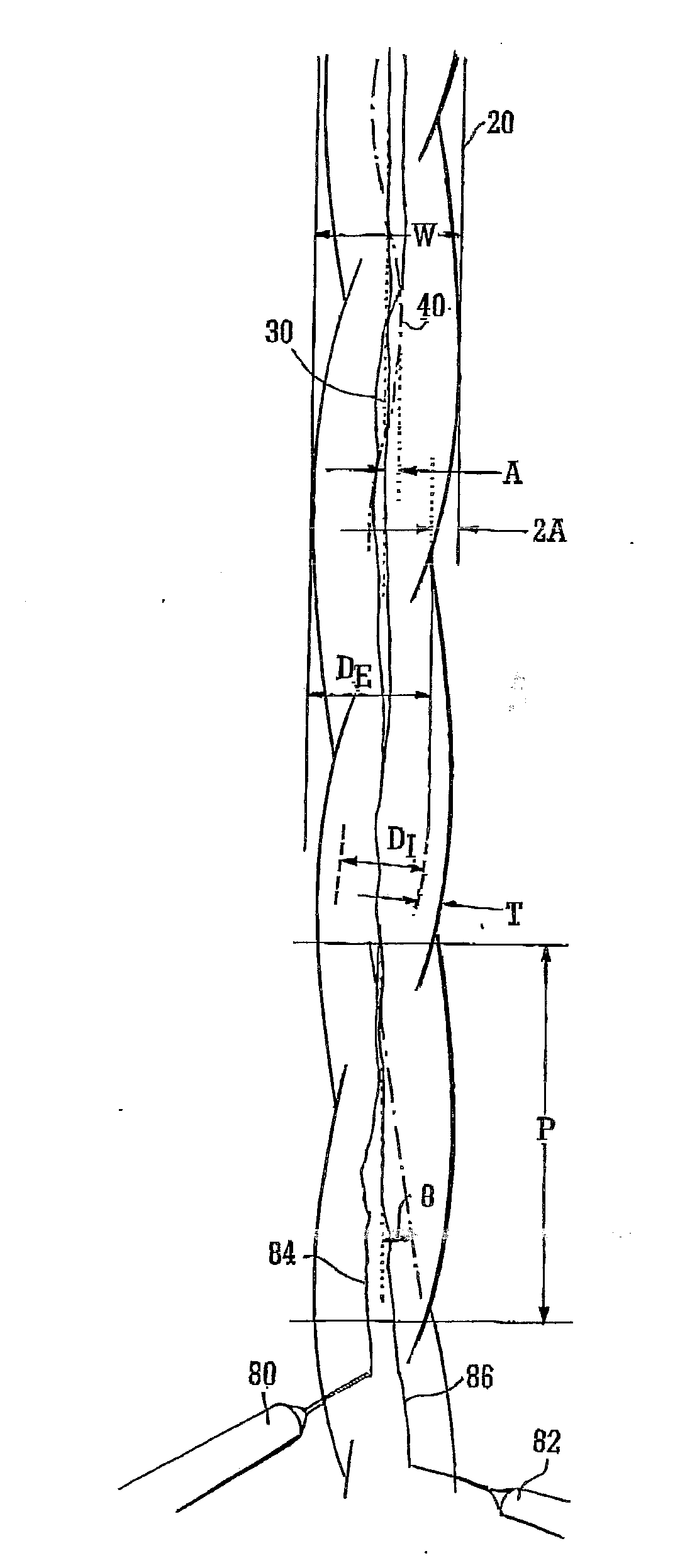
[0131]Experiments were carried out using polyvinyl chloride tubing with a circular cross-section. Referring to the parameters shown in FIG. 1 the tubing had an external diameter DE of 12 mm, an internal diameter DI of 8 mm and a wall thickness T of 2 mm. The tubing was coiled into a helix with a pitch P of 45 mm and a helix angle θ of 8°. The amplitude A was established by resting the tubing between two straight edges and measuring the space between the straight edges. The amplitude was determined by subtracting the external diameter DE from the swept width W:

2A=W−DE

So:

[0132]A=W-DE2

[0133]In this example the swept width W was 14 mm, so:

A=W-DE2=14-122=1mm

[0134]As discussed earlier, “relative amplitude” AR is defined as:

AR=ADr

[0135]In the case of this Example, therefore:

AR=ADr=18=0.125

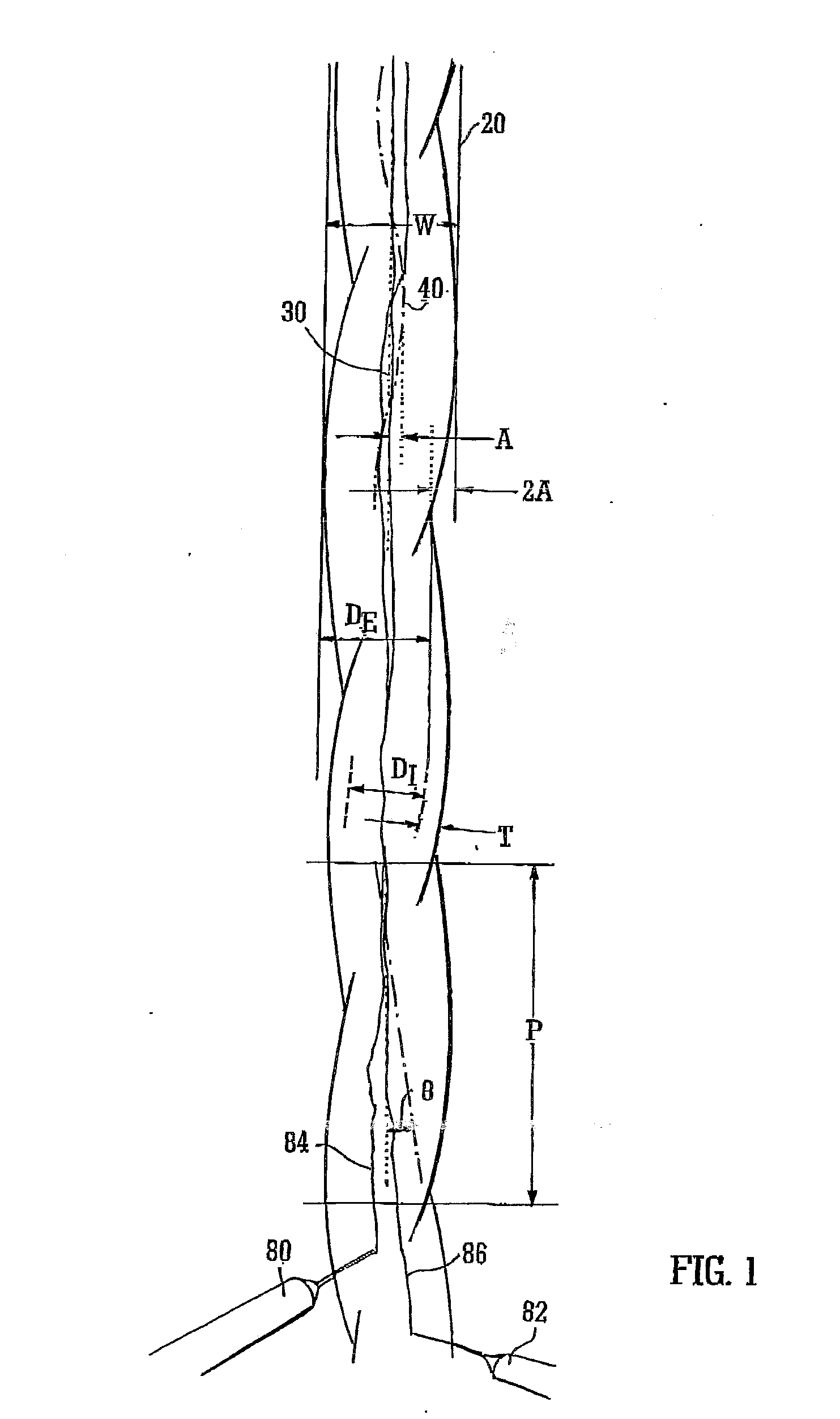
[0136]Water was passed along the tube. In order to observe the flow characteristics, two needles 80 and 82 passing radially through the tube wall were used to inject visible dye into the flow. The inject...

example 2

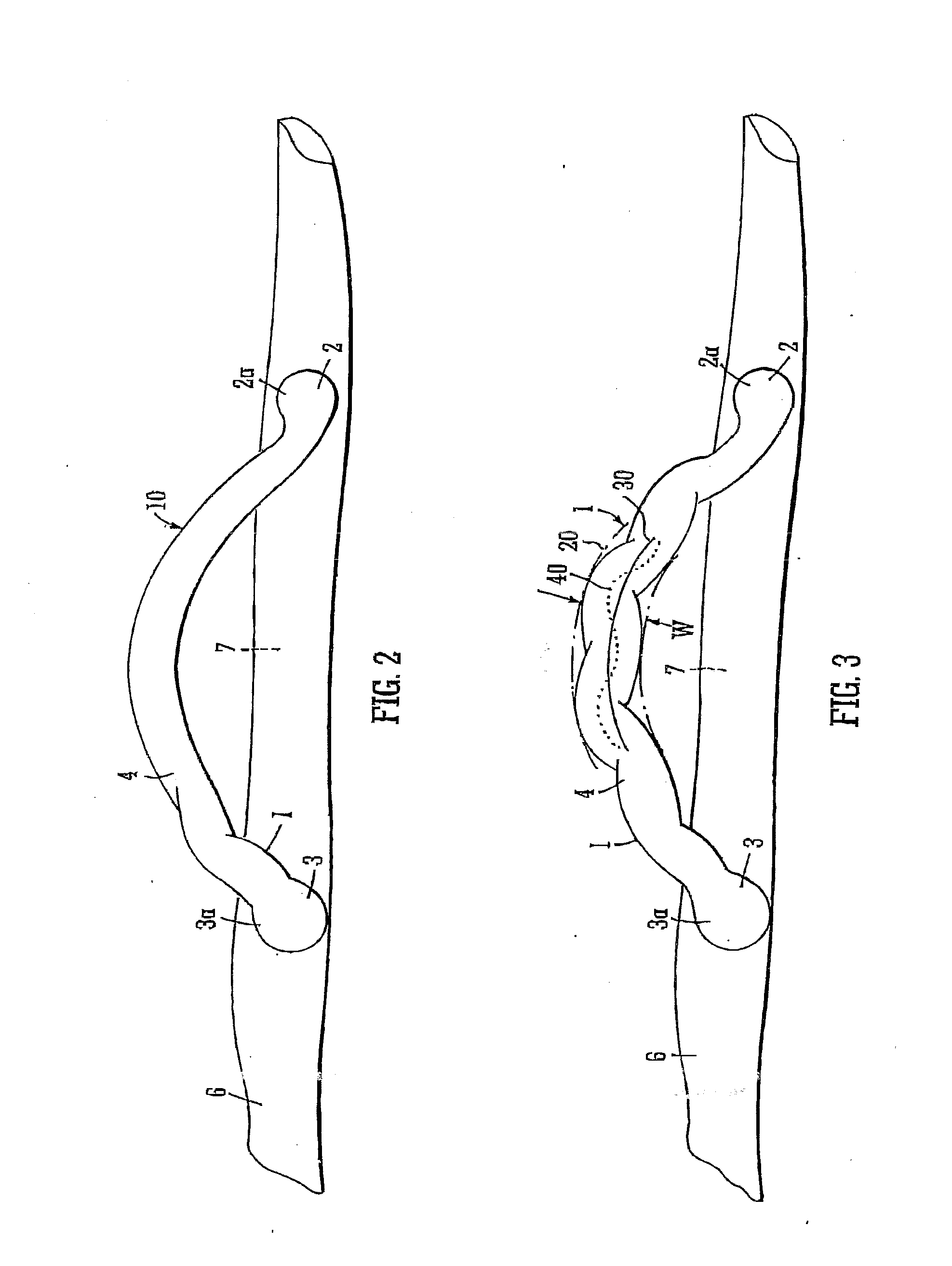
[0138]The parameters for this Example were the same as in Example 1, except that the needles 80 and 82 were arranged to release the ink filaments 84 and 86 near to the wall of the tubing. FIG. 15 shows the results of two experiments with near-wall ink release, with Reynolds numbers RE of 500 and 250 respectively. It will be seen that in both cases the ink filaments follow the helical tubing geometry, indicating near-wall swirl. Furthermore, mixing of the ink filaments with the water is promoted.

[0139]It will be appreciated that this invention, in its first aspect, is concerned with values of relative amplitude AR less than or equal to 0.5, i.e. small relative amplitudes. In a straight tubing portion both the amplitude A and the relative amplitude AR equal zero, as there is no helix. Therefore, with values of relative amplitude AR approaching zero, the ability of the tubing portion to induce swirl will reduce. The lowest workable value of relative amplitude AR for any given situation...


PUM

PropertyMeasurementUnit
helix angleaaaaaaaaaa
angleaaaaaaaaaa

Abstract

A graft includes a flow tubing having a tubing portion defining a flow lumen. The flow lumen of the tubing portion is substantially free of ribs or grooves. A centre line of the flow lumen follows a substantially helical path with a helix angle less than or equal to 65°. The amplitude of the helix is less than or equal to one half of the internal diameter of the tubing portion.

Description

[0001]This application is a divisional application of U.S. Ser. No. 10 / 549,498 which was filed on Aug. 14, 2006 and is still pending.BACKGROUND OF THE DISCLOSURE[0002]This invention relates to grafts.[0003]We have previously proposed that the flow pattern in arteries including the swirling pattern induced by their non-planar geometry operates to inhibit the development of vascular diseases such as thrombosis, atherosclerosis and intimal hyperplasia.[0004]It is known from WO 95 / 09585 to provide a vascular prosthesis comprising a length of generally hollow tubing having openings at both ends thereof and including a non-planar curved portion so as to induce swirl flow in blood flowing through the curved portion. As explained in that publication, the swirl flow induced by skewing of the blood flow within the non-planar curved portion improves flow characteristics and reduces the potential for deposit build-up and vascular disease including intimal hyperplasia.[0005]In WO 98 / 53764, there...

Claims


Application Information

Patent Timeline
Patent Type & Authority Applications(United States)
IPC IPC(8): B29C53/14A61F2/06B29C65/00
CPCB29C53/14A61F2/06B29C65/00A61F2002/068A61F2002/91516A61F2/915A61F2002/91508
Inventor CARO, COLIN G.WATKINS, NICHOLAS V.SHERWIN, SPENCER J.
Owner VERYAN MEDICAL LTD
Why Eureka
Try Eureka