Rotary electric machine and stator manufacturing method

Active Publication Date: 2014-08-14
TOYOTA JIDOSHA KK
View PDF5 Cites 37 Cited by
  • Summary
  • Abstract
  • Description
  • Claims
  • Application Information

AI Technical Summary

Benefits of technology

[0021]The rotary electric machine in one aspect of the invention having the above characteristics can provide the following operations and advantageous effects.
[0022]The above aspect described in (1) is a rotary electric machine comprising a stator including: a segment coil having a plurality of segments formed of a flat rectangular conductor subjected to bending; and a stator core having slots in which the segment coil is inserted, wherein welded parts formed at tips of lead sections of the segment coil, the lead sections protruding out of an end face of the stator core and being twisted, include weld beads arranged in a radial direction of the stator, at least one of the weld beads having a long ellipsoidal shape that is long in a radial direction of the stator core, and an angle between a longitudinal direction of the long ellipsoidal shape and an axial direction of the stator core is smaller than 90 degrees on a core cross section including a central axis of the stator core. Specifically, each weld bead formed to bridge over the tips of the adjacent lead sections is formed in a long ellipsoidal shape.
[0023]This configuration can make the adjacent weld beads hard to contact with each other when the adjacent tips of the lead sections are welded to form the weld beads. The coil end section of the stator is desired to be compact in size in association with a demand for size reduction of a rotary electric machine. The lead sections are bent in a twisting process so that the lead tip portions are placed in close positions. However, a jig called a twisting ring to be used in this twisting process needs a little gap between the lead sections when it is to be inserted. If a short distance between the lead sections may cause contact between the weld beads, the lead sections have to be spaced at a predetermined distance.
[0024]In designing the end portions of the stator, it is necessary to minimi

Problems solved by technology

Those vehicle-mounted drive motors are demanded for small footprint due to limited mounting space.
In particular, a hybrid

Method used


Image

  • Rotary electric machine and stator manufacturing method
  • Rotary electric machine and stator manufacturing method
  • Rotary electric machine and stator manufacturing method

Examples


Example

[0058]A detailed description of a first embodiment of the present invention will now be given referring to the accompanying drawings.

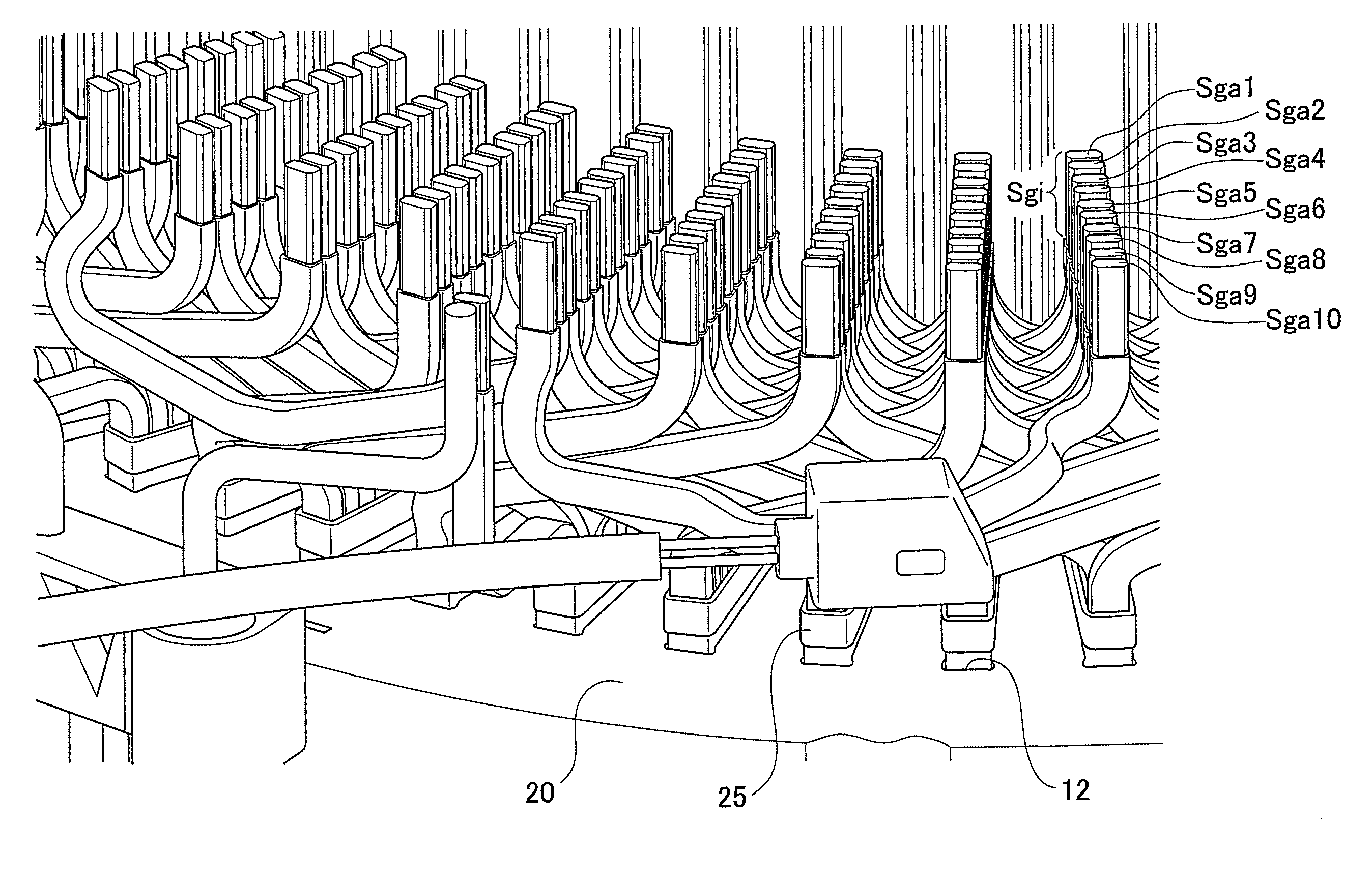
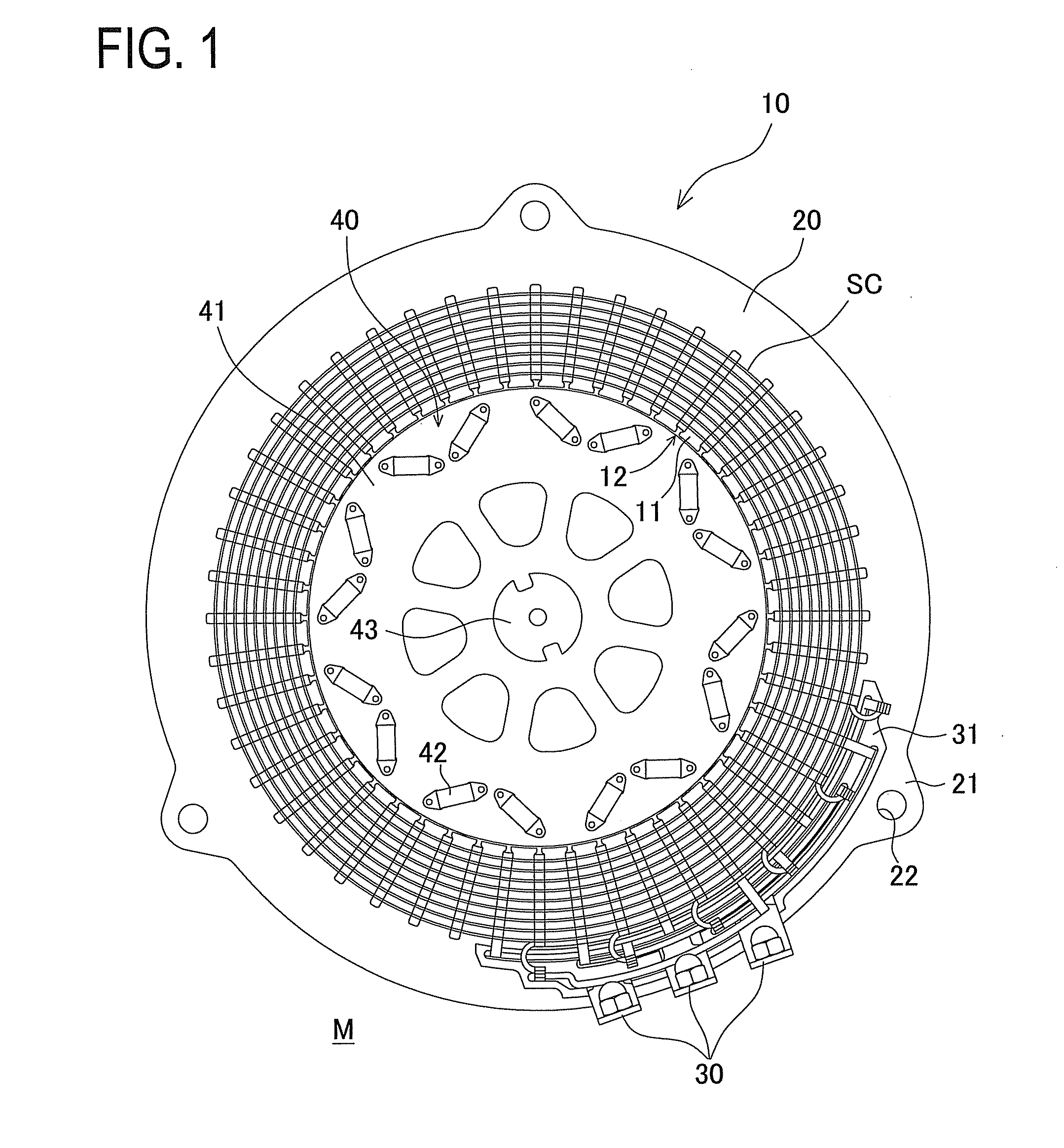
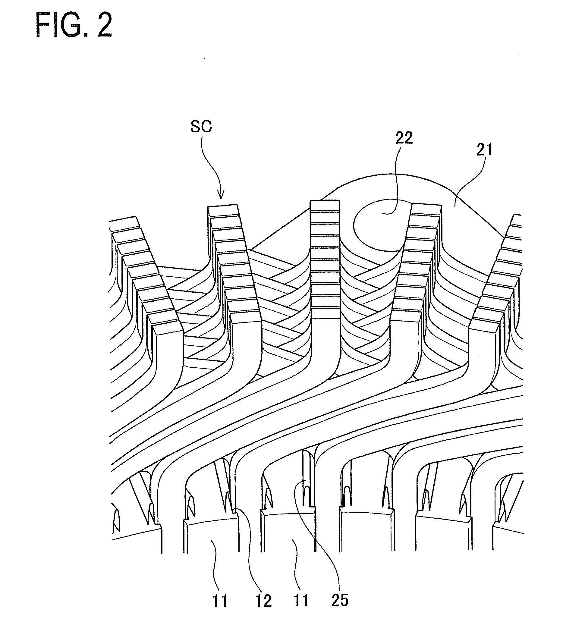
[0059]FIG. 1 is a plan view of a rotary electric machine M in the first embodiment. FIG. 2 is an enlarged perspective view of a coil end section on a lead side of a stator 10. However, a rotor 40 is omitted from FIG. 2 for convenience of explanation. The stator 10 includes a stator core 20 and a segment coil SC. The stator core 20 made of electromagnetic steel sheets laminated into a nearly cylindrical shape is formed with teeth 11 each protruding on an inner circumferential side of the stator core 20 and slots 12 defined between adjacent teeth 11.

[0060]The number of the teeth 11 provided in the stator core 20 is 48. The number of the slots 12 provided herein is also 48. The outer edge of the stator core 20 has ribs 21 formed to protrude outward from the stator core 20 and bolt holes 22 provided one in each of the ribs 21. These bolt holes 22 are avail...

Example

[0085]Next, a second embodiment of the invention will be explained referring to drawings. The second embodiment is almost identical in configuration to the stator 10 of the first embodiment, excepting setting of heights of the lead sections Sga. The following explanation is given to this difference by use of the drawings.

[0086]FIG. 19 is a side view of tip portions of the lead sections Sga having different heights in the second embodiment. FIG. 20 is a side view showing the welded tip portions of the lead sections Sga having different heights. The difference from the first embodiment is in setting the even-numbered lead sections Sga arranged radially outward in the stator 10, that is, the second lead section Sga2, the fourth lead section Sga4, the sixth lead section Sga6, the eighth lead section Sga8, and the tenth lead section Sga10 so as to be higher than respective adjacent lead sections Sga.

[0087]This difference in height between the lead sections Sga is achieved by adjusting th...

Example

[0089]Next, a third embodiment of the invention will be explained referring to drawings. The third embodiment is almost identical in configuration to the stator 10 of the first embodiment, excepting the shape of each tip of the lead section Sga. The following explanation is given to this difference by use of the drawings.

[0090]FIG. 21 is a side view of tip portions of the lead sections Sga in the third embodiment. FIG. 22 is a side view showing the welded tip portions of the lead sections Sga. It is to be noted that the lead sections Sga shown in FIGS. 21 and 22 are illustrated by four located on the inner circumferential side of the stator 10, and remaining lead sections are omitted. In the third embodiment, different from the first embodiment, the shapes of the lead sections Sga of the segments Sg have different shapes from adjacent lead sections Sga. As shown in FIG. 21, a first peeled portion Sgi1 of the first lead section Sga1 and a third peeled portion Sgi3 of the third lead s...


PUM

PropertyMeasurementUnit
Angleaaaaaaaaaa
Heightaaaaaaaaaa

Abstract

In order to provide a rotary electric machine with a reduced size and improved weldability, the stator of a rotary electric machine has a segment coil formed by bending rectangular conductors, and a stator core having slots in which the segment coil is inserted. As for the weld parts formed at the tips of the lead parts of the segment coil which protrude from the end face of the stator core and are twisted together, at least one of the weld beads aligned in the radial direction of the stator is an oblong body that is long in the radial direction of the stator core, and the angle formed by the longitudinal direction of the oblong body and the axial direction of the stator core is less than 90 degrees in a core cross section that includes the central axis of the stator core.

Description

TECHNICAL FIELD[0001]The present invention relates to a technique to produce a stator using a segment coil and more particularly to a technique to insert a segment coil in slots of a stator and then weld end portions of the segment coil to each other.BACKGROUND ART[0002]Recently, in more and more cases, drive motors are mounted in vehicles in view of environmental concerns. Those vehicle-mounted drive motors are demanded for small footprint due to limited mounting space. Further, those motors are requested to output high power in order to enhance drive performance of the vehicles. In particular, a hybrid car has to mount therein both an engine and a drive motor in an engine room and is subjected to severe space limitations.[0003]To reduce the size and increase output power of both a motor and a rotary electric machine, it is conceived to increase electric current values supplied to a coil provided in a stator. However, this needs a sufficient cross sectional area of a coil used in a...

Claims


Application Information

Patent Timeline
IPC IPC(8): H02K3/28H02K15/04
CPCH02K15/0414H02K3/28B23K9/167H02K3/12H02K15/0081Y10T29/49009B23K2101/38
Inventor GOTO, KAZUHIRO
Owner TOYOTA JIDOSHA KK
Why Eureka
Try Eureka