Proximity sensor

a proximity sensor and magnetic field technology, applied in the field of magnetic proximity sensors, can solve the problems of loss of magnetic flux equilibrium, difficult to put this conventional proximity sensor into practice, and inability to meet the magnetic flux of two magnets in a region of magnetic detection elements. to achieve the effect of high accuracy

Active Publication Date: 2014-08-14
VALEO JAPAN CO LTD
View PDF12 Cites 5 Cited by
  • Summary
  • Abstract
  • Description
  • Claims
  • Application Information

AI Technical Summary

Benefits of technology

[0010]According to the aspect of the present invention, the proximity sensor can be formed of a simple structure comprising a fewer components by adopting the single magnet, and therefore can realize the detection with high accuracy by solving the problem of the variation in characteristics of the magnet that is unavoidable at the time of requiring a plurality of magnets. Further, since a set of the additional first yoke and the magnetic responsive element is shifted in the relative movement direction to the detected member to be provided between the magnet and the second yoke, the position of the detected member can be detected by a plurality of steps.

Problems solved by technology

However, in the conventional proximity sensor, at least two magnets are required to be mounted to the first yoke to make the magnetic poles opposing with each other differ, and therefore, for preventing the event that a magnetic contamination substance is attached to the magnet at the time of the assembly of the sensor in a manufacturing line or the like and the equilibrium of the magnetic flux is lost regardless of the detected member is not positioned to be close to the sensor, the strict environment and the process management in the manufacturing line or the like are required.
In addition, since the permanent magnet originally varies a lot in the magnetic force depending on its individual, even if the assembly of the sensor in the manufacturing line is strictly managed, the magnetic fluxes of the two magnets in a region of the magnetic detection element do not necessarily come to equilibrium or change as desired.
However, any adjustment measure is not taken for overcoming this problem, and therefore it is still difficult to put this conventional proximity sensor into practice.

Method used


Image

  • Proximity sensor
  • Proximity sensor
  • Proximity sensor

Examples


first embodiment

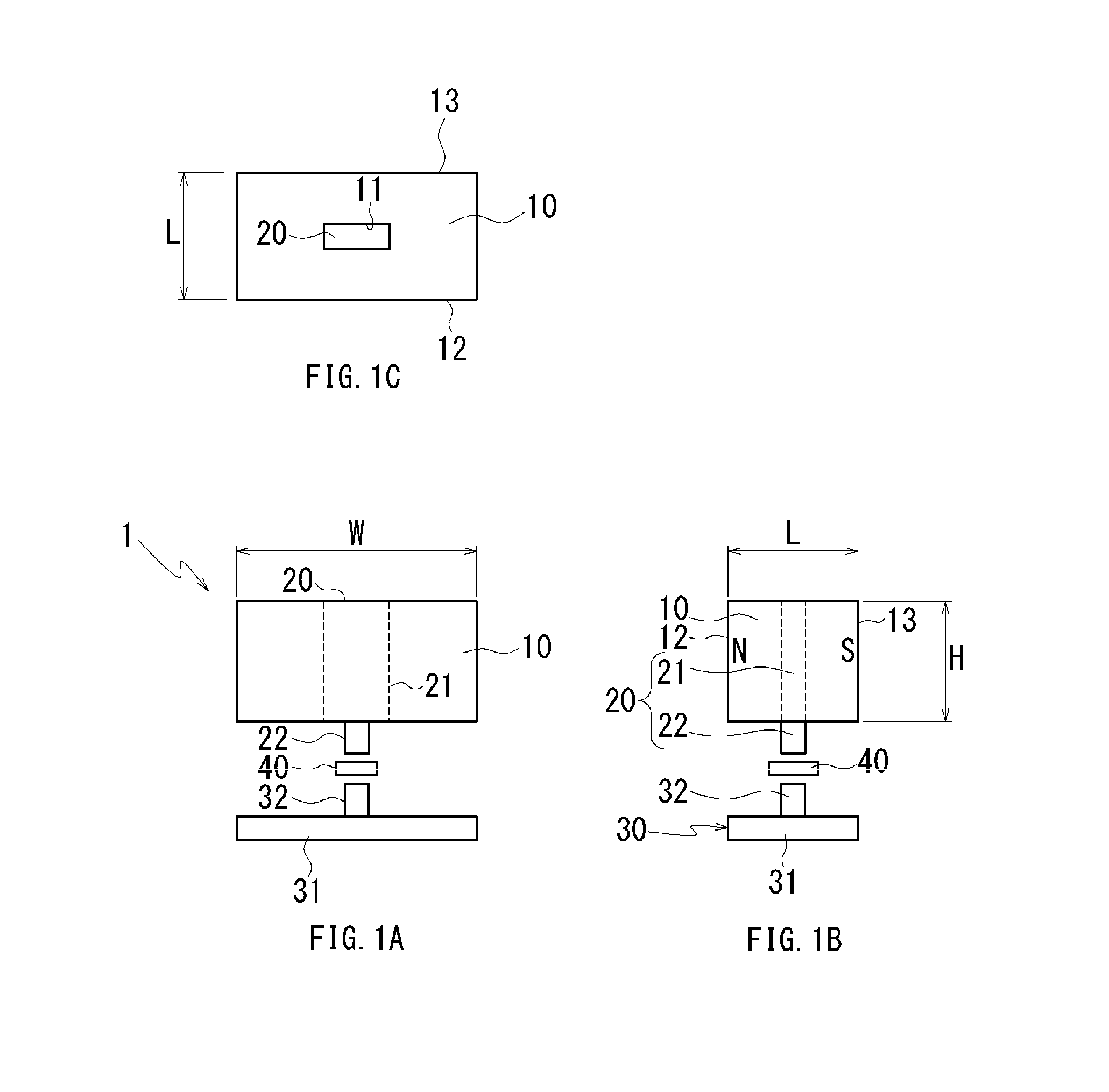
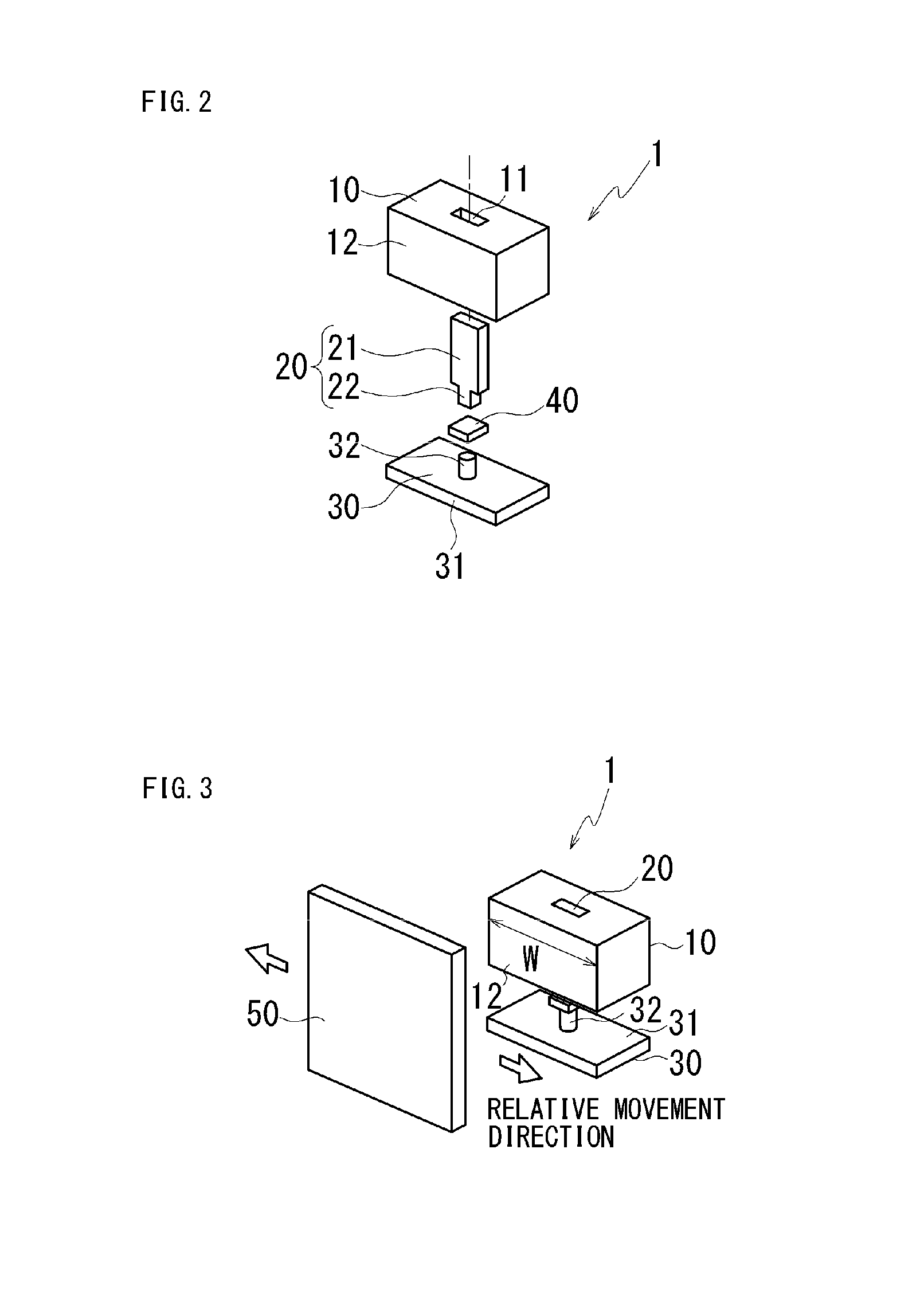
[0026]FIG. 1A is a front view showing the configuration of a proximity sensor according to a first embodiment, FIG. 1B is a side view thereof, and FIG. 1C is a top view thereof. FIG. 2 is an exploded perspective view of the proximity sensor according to the first embodiment. A proximity sensor 1 comprises a permanent magnet (hereinafter, called a magnet) 10, a first yoke 20 held by the magnet 10, a hall IC 40 as a magnetic responsive element, and a second yoke 30. The magnet 10, as shown in FIG. 1B, has N pole and S pole at both ends in the right and left, and is formed in a rectangular parallelepiped having magnetic pole faces 12 and 13 each having a width W and a height H, and a length L. The first yoke 20 is held in a holding hole 11 of a rectangular traverse section that is formed in the center of the magnet 10 and penetrates from a top face to a bottom face thereof.

[0027]The first yoke 20 includes a fixed primary portion 21 that is formed in a plate shape and has the same heigh...

second embodiment

[0049]Next, a proximity sensor according to a second embodiment in the present invention will be explained.

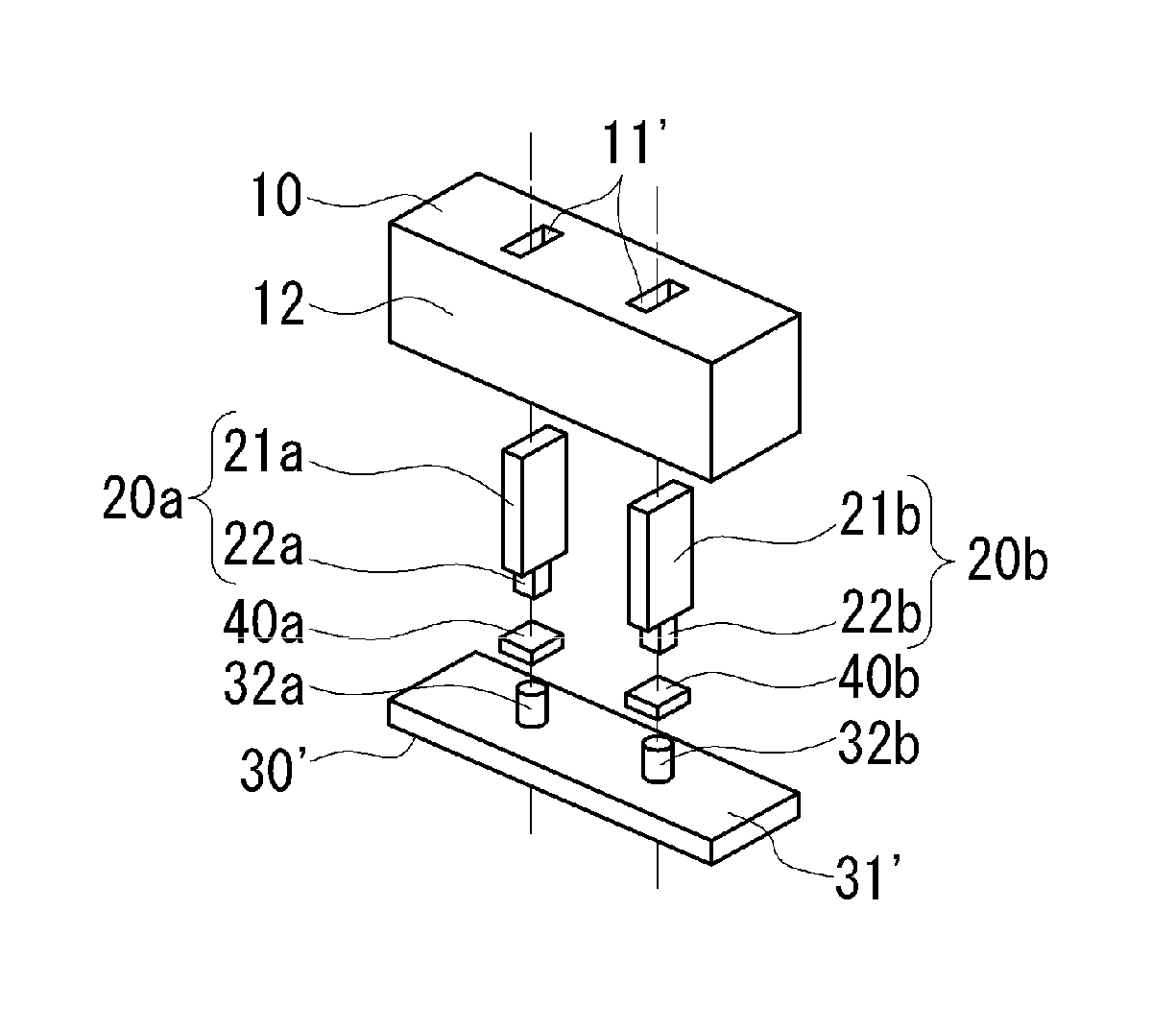
[0050]FIG. 10A is a front view showing the configuration of a proximity sensor according to a second embodiment, FIG. 10B is a side view thereof, and FIG. 10C is a top view thereof. FIG. 11 is an exploded perspective view of the proximity sensor according to the second embodiment. A proximity sensor 1A in the second embodiment comprises a permanent magnet 10′, two first yokes 20a and 20b held by the magnet 10′, two hall IC 40a and 40b, and a second yoke 30′. The magnet 10′, in FIG. 10B, has N pole and S pole at both ends in the right and left, and is formed in a rectangular parallelepiped having magnetic pole faces 12′ and 13′ each having a width W and a height H, and a length L. Herein the width (W) dimension is longer than the magnet in the first embodiment. Holding holes 11′ each having a rectangular traverse section are provided at both sides of the magnet 10′ having the ce...


PUM


Abstract

A proximity sensor with high accuracy without being subject to an influence due to magnet variations is disclosed. A first yoke is insert-molded in an intermediate position between N and S poles of a magnet, and a projecting portion of the first yoke projects from a wall face of the magnet vertically to a magnetic pole face. A protruding portion of a second yoke opposes the projecting portion to arrange a main body portion in parallel with the wall face of the magnet, and a hall IC having a direction of connecting the projecting portion and the protruding portion as a magnetic responsive direction is arranged in a space between the projecting portion and the protruding portion.

Description

BACKGROUND OF THE INVENTION[0001]1. Field of the Invention[0002]The present invention relates to a magnetic proximity sensor for detecting a position of a detected body in non-contact.[0003]2. Description of the Related Art[0004]This type of proximity sensor causes an increasing interest as a sensor that is excellent in a point that there does not exist degradation of the contact point due to contact that is made in a so-called contact point type switch. Therefore, for example, as an application of this type of proximity sensor to a vehicle, a pedal sensor, a door opening / closing sensor, a hood opening / closing sensor, a seat position sensor, a seat belt strapping sensor, and the like are under consideration. For example, Japanese Patent No. 4066716 discloses the conventional proximity sensor as follows. This proximity sensor comprises at least two opposing permanent magnets (hereinafter, called simply a magnet), a first yoke interposed between magnetic pole faces thereof, a protrudi...

Claims


Application Information

Patent Timeline
Patent Type & Authority Applications(United States)
IPC IPC(8): G01B7/00
CPCG01B7/003H03K17/9505H03K17/9517G01D5/147
Inventor SATO, SHUNICHI
Owner VALEO JAPAN CO LTD
Why Eureka
Try Eureka