Electronic endoscope system

a technology of electronic endoscope and insert section, which is applied in the field of electronic endoscope system, can solve the problems of increasing the noise of dark current from the image sensor, conspicuous white defective pixel (the so-called white spot), and deteriorating observation image, so as to achieve the effect of preventing the increase in the diameter of the insert section and simplifying the structure of the electronic endoscop

Inactive Publication Date: 2014-08-14
FUJIFILM CORP
View PDF20 Cites 15 Cited by
  • Summary
  • Abstract
  • Description
  • Claims
  • Application Information

AI Technical Summary

Benefits of technology

[0017]In the present invention, the temperature is detected from the output of the image sensor. This eliminates the need for the temperature sensor. As a result, a structure of the electronic endoscope is simplified, and increase in diameter of the insert section is prevented.

Problems solved by technology

As a result, dark current noise from the image sensor increases, which makes a white defective pixel (the so-called white spot) conspicuous.
Thus, the observation image is deteriorated.
As a result, the imaging signal may be saturated.
However, installation of the temperature sensor and the signal transmission lines in the distal portion require additional space.
As a result, when the electronic endoscope is for medical use, physical stress of a patient increases.
When the light quantity of the illumination light is excessively reduced in accordance with the temperature of the distal portion, an observation image may become too dark for diagnosis.

Method used


Image

  • Electronic endoscope system
  • Electronic endoscope system
  • Electronic endoscope system

Examples


Embodiment Construction

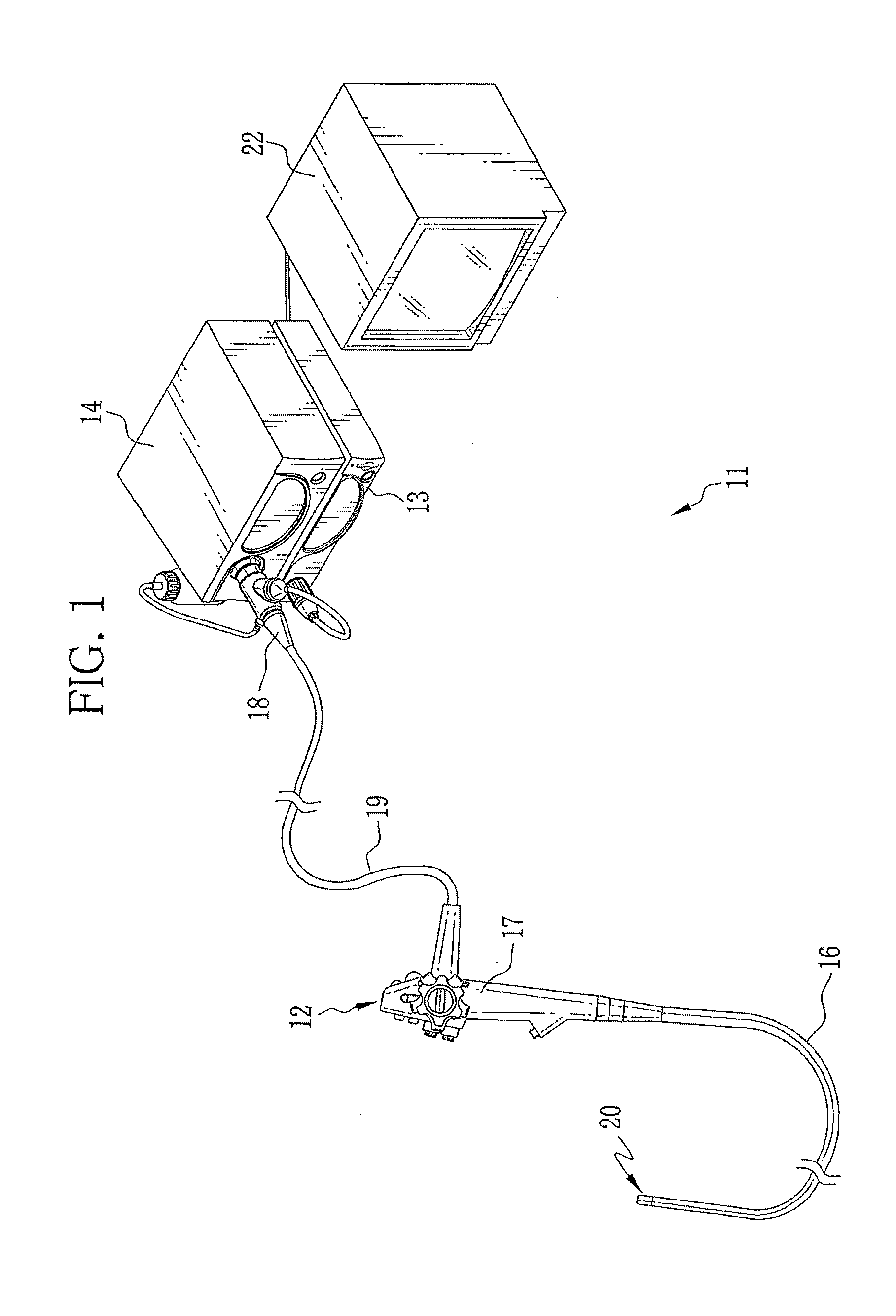
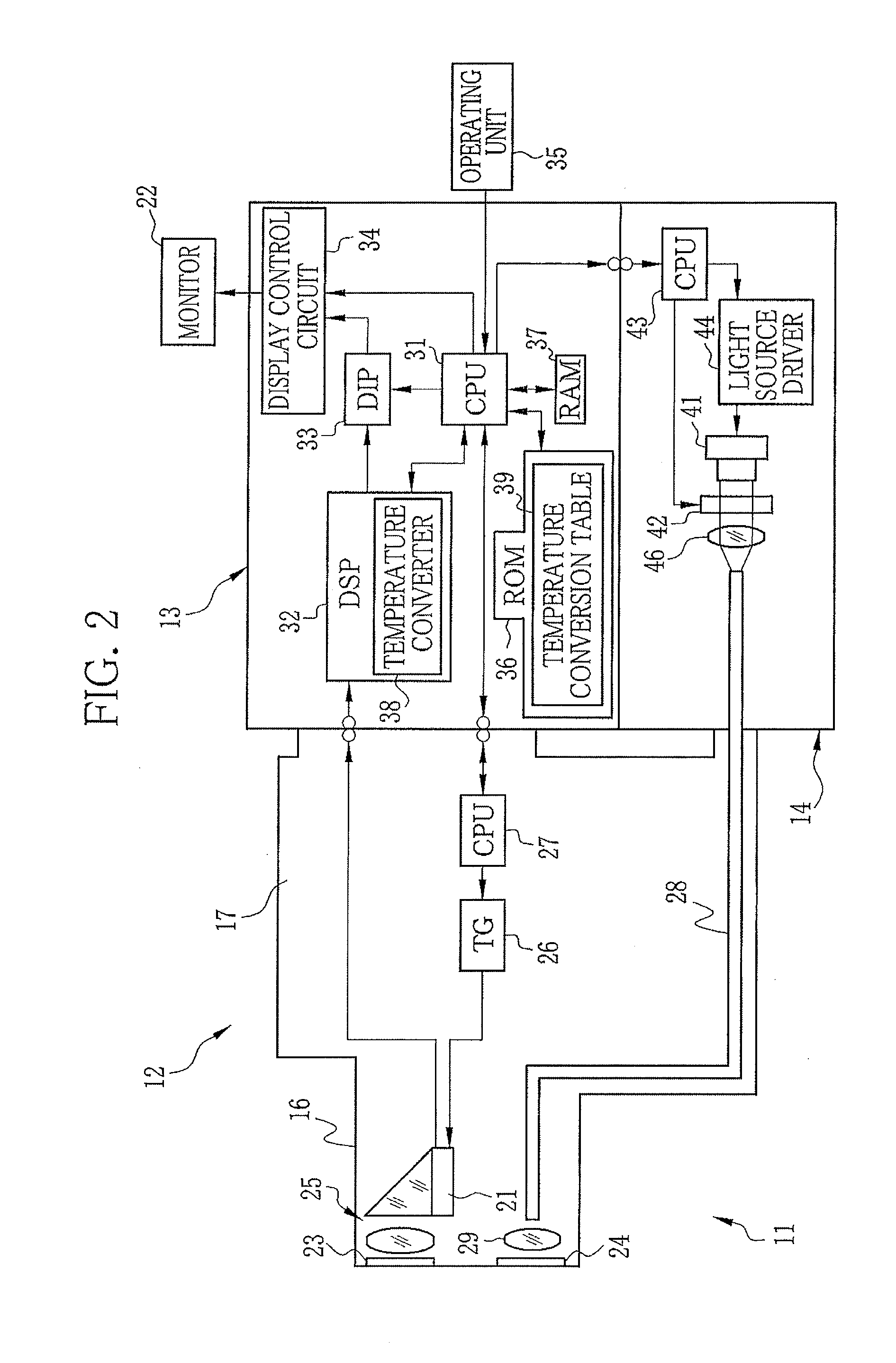
[0033]In FIG. 1, an electronic endoscope system 11 is composed of an electronic endoscope 12, a processing apparatus 13, and a light source apparatus 14. The electronic endoscope 12 is for medical use, for example, and has a flexible insert section 16 to be inserted into an interior of a patient's body, an operation section 17 connected to a base portion of the insert section 16, a connector 18 connected to the processing apparatus 13 and the light source apparatus 14, and a universal cord 19 connecting the operation section 17 and the connector 18. As shown in FIG. 2, a distal end (hereinafter referred to as the distal portion) 20 of the insert section 16 is provided with an imaging device, for example, a CMOS image sensor (hereinafter referred to as the CMOS sensor) 21.

[0034]The operation section 17 is provided with operation members such as an angle knob for directing the distal portion 20 in vertical and horizontal directions, an air / water button for ejecting air and water from ...


PUM


Abstract

An electronic endoscope system is composed of an electronic endoscope, a light source apparatus, and a temperature converter. The electronic endoscope has a CMOS sensor in a distal portion of an insert section to be inserted into a patient's body cavity. Illumination light from the light source apparatus is applied to the body cavity through the distal portion. The temperature converter obtains an average pixel value of an optical black (OB) region out of an imaging signal from the CMOS sensor, and converts the average OB pixel value into a temperature of the CMOS sensor on a frame-by-frame basis with the use of data in a temperature conversion table. The table represents a relationship between the average OB pixel value and the temperature of the CMOS sensor. Light quantity of the illumination light is adjusted in accordance with the temperature of the CMOS sensor to prevent deterioration of image quality.

Description

CROSS REFERENCE TO RELATED APPLICATION[0001]This is a Divisional of U.S. application Ser. No. 13 / 196,433 filed Aug. 2, 2011, which claims priority from JP 2010-174179, filed Aug. 3, 2010, the disclosures of all which are hereby incorporated by reference.FIELD OF THE INVENTION[0002]The present invention relates to an electronic endoscope system for capturing an image of an interior of an object using an image sensor.DESCRIPTION RELATED TO THE PRIOR ART[0003]An examination of an object using an electronic endoscope system is commonly performed in medical and industrial fields. The electronic endoscope system is composed of an electronic endoscope, a processing apparatus connected to the electronic endoscope, alight source apparatus, and the like. The electronic endoscope has an insert section to be inserted into an interior of the object.[0004]The electronic endoscope has a distal portion at a distal end of the insert section. The distal portion includes an illumination window for app...

Claims


Application Information

Patent Timeline
Patent Type & Authority Applications(United States)
IPC IPC(8): A61B1/00H04N5/361H04N5/374A61B1/06
CPCA61B1/00009H04N5/374H04N5/361A61B1/0661A61B1/0002A61B1/05A61B1/128H04N25/63H04N25/76
Inventor ASHIDA, TSUYOSHIMURAYAMA, JINNAKAMURA, TAKAYUKIHIRATA, HIDETOSHIHARA, KAZUYOSHIYAMAKAWA, SHINICHIIIDA, TAKAYUKI
Owner FUJIFILM CORP
Why Eureka
Try Eureka