Autonomous fluid control device having a reciprocating valve for downhole fluid selection

Active Publication Date: 2014-08-21
HALLIBURTON ENERGY SERVICES INC
View PDF3 Cites 9 Cited by
  • Summary
  • Abstract
  • Description
  • Claims
  • Application Information

AI Technical Summary

Benefits of technology

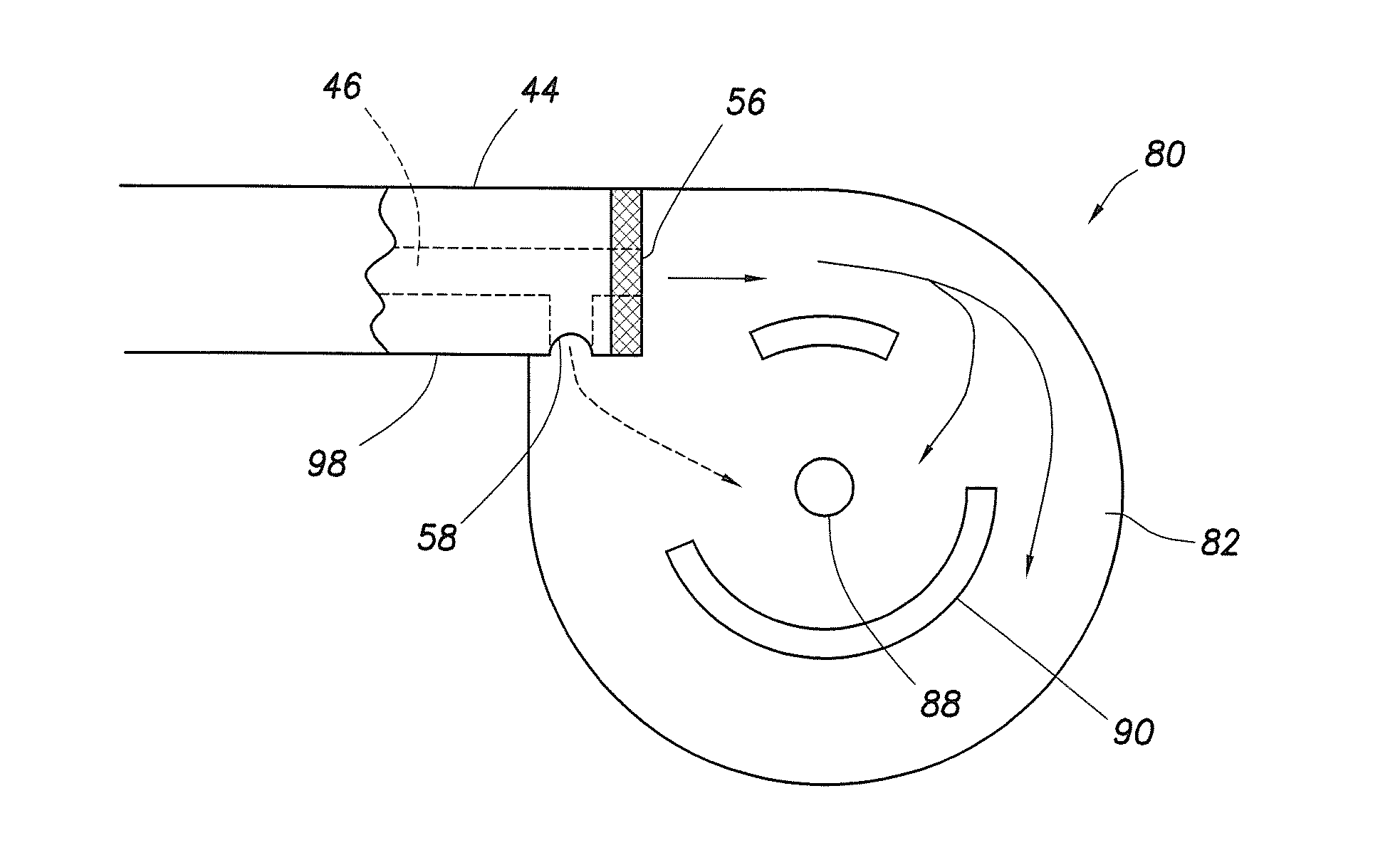
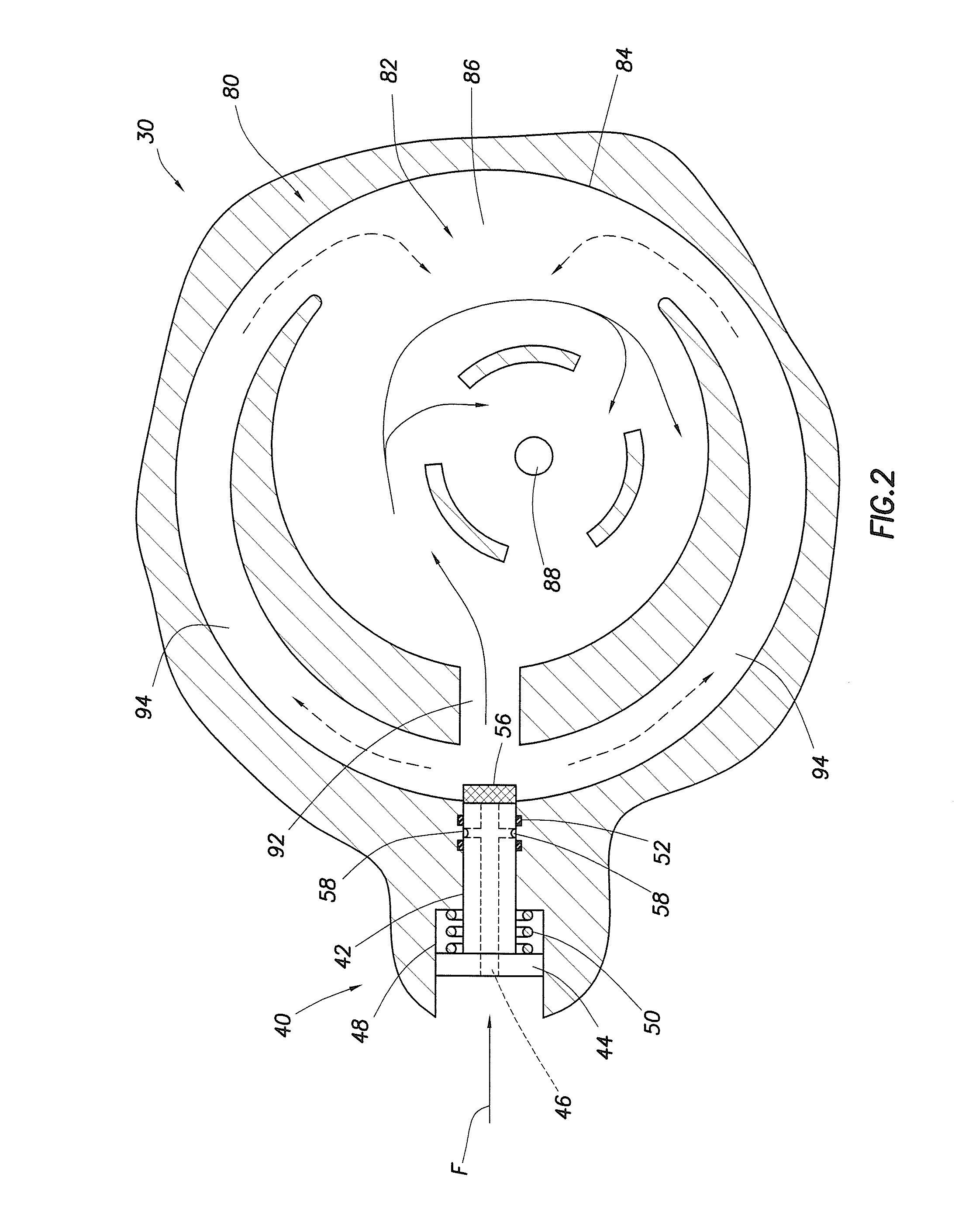
The invention is about a device that can change the way fluid flows in a chamber, by moving a part back and forth. When the part is in one position, the fluid flows in a way that causes pressure drop and increases the fluid velocity. When the part is in another position, the fluid flows in a way that reduces pressure drop and velocity. The technical effect of this invention is that it can control the flow of fluid in a chamber, which can be useful in various applications such as power generation.

Problems solved by technology

Similar issues arise with regard to injection situations, with flow of fluids going into instead of out of the formation.

Method used


Image

  • Autonomous fluid control device having a reciprocating valve for downhole fluid selection
  • Autonomous fluid control device having a reciprocating valve for downhole fluid selection
  • Autonomous fluid control device having a reciprocating valve for downhole fluid selection

Examples


Embodiment Construction

[0015]While the making and using of various embodiments of the present invention are discussed in detail below, a practitioner of the art will appreciate that the present invention provides applicable inventive concepts which can be embodied in a variety of specific contexts. The specific embodiments discussed herein are illustrative of specific ways to make and use the invention and do not limit the scope of the present invention.

[0016]Descriptions of fluid flow control using autonomous flow control devices and their application can be found in the following U.S. Patents and Patent Applications, each of which are hereby incorporated herein in their entirety for all purposes: U.S. Pat. No. 7,404,416, entitled “Apparatus and Method For Creating Pulsating Fluid Flow, And Method of Manufacture For the Apparatus,” to Schultz, filed Mar. 25, 2004; U.S. Pat. No. 6,976,507, entitled “Apparatus for Creating Pulsating Fluid Flow,” to Webb, filed Feb. 8, 2005; U.S. patent application Ser. No....


PUM


Abstract

An apparatus and method autonomously controls fluid flow in a subterranean well, as the fluid changes in a characteristic, such as viscosity, over time. An autonomous reciprocating member has a fluid flow passageway there through and a primary outlet and at least one secondary outlet. A flow restrictor, such as a viscosity dependent choke or screen, is positioned to restrict fluid flow through the primary outlet. A vortex chamber is positioned adjacent the reciprocating member. The reciprocating member moves between a first position where fluid flow is directed primarily through the primary outlet of the reciprocating member and into the primary inlet of the vortex assembly, and a second position where fluid flow is directed primarily through the at least one secondary outlet of the reciprocating member and into the at least one secondary inlet of the vortex assembly. The movement of the reciprocating member alters the fluid flow pattern in the adjacent vortex chamber.

Description

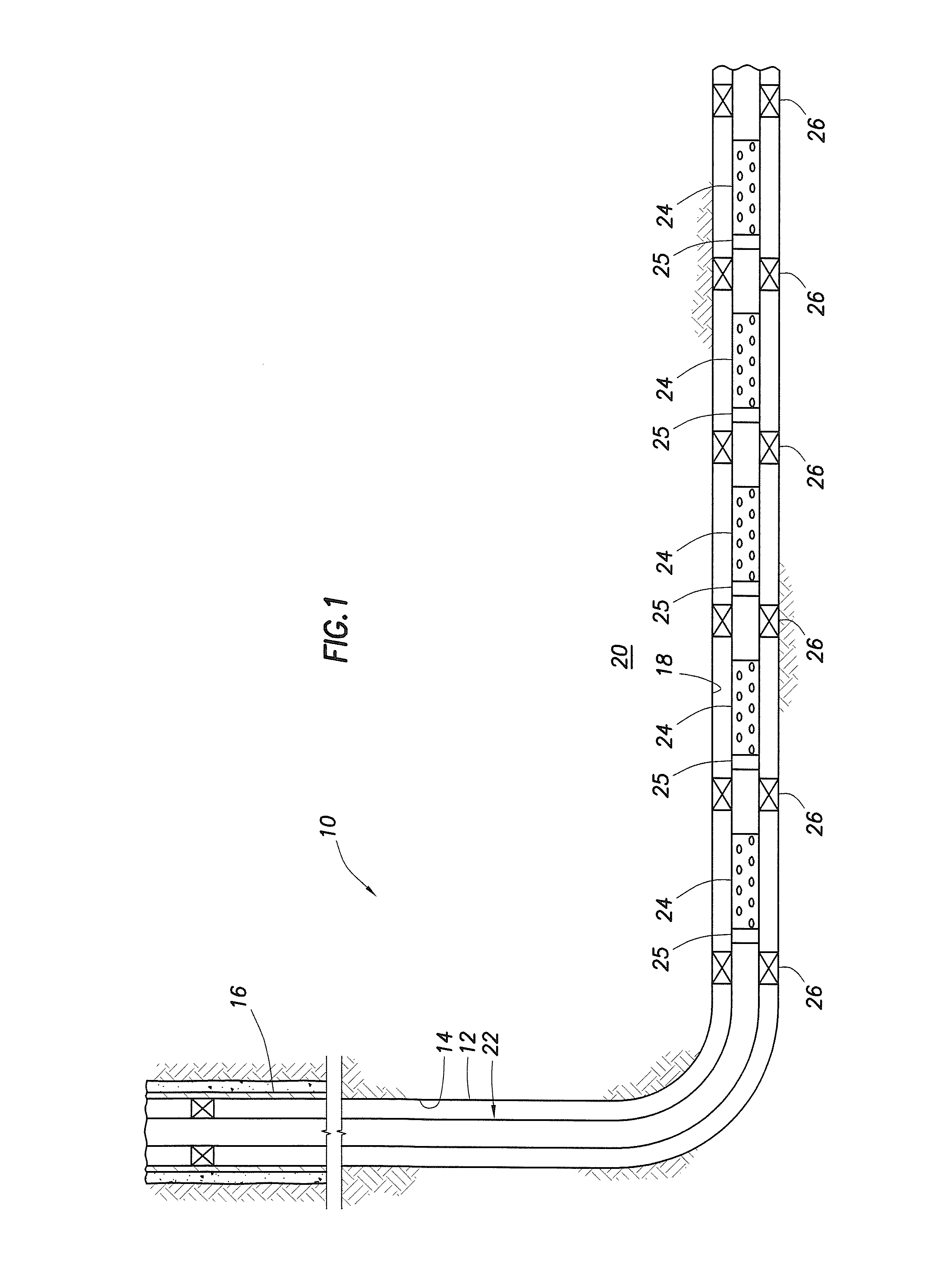
CROSS-REFERENCE TO RELATED APPLICATIONS[0001]None.FIELD OF INVENTION[0002]The invention relates generally to methods and apparatus for selective control of fluid flow from a formation in a hydrocarbon bearing subterranean formation into a production string in a wellbore. More particularly, the invention relates to methods and apparatus for controlling the flow of fluid based on some characteristic of the fluid flow, such as viscosity, by utilizing a reciprocating member, such as a hollow-bore piston having a screen covering or choke at one end of the bore, the reciprocating member moved to an open position by the force of a flowing fluid depending on a characteristic of the fluid, for example, by the force of a relatively higher viscosity fluid.BACKGROUND OF INVENTION[0003]During the completion of a well that traverses a hydrocarbon bearing subterranean formation, production tubing and various equipment are installed in the well to enable safe and efficient production of the fluids....

Claims


Application Information

Patent Timeline
IPC IPC(8): E21B34/08
CPCE21B34/08E21B43/12
Inventor GRECI, STEPHEN
Owner HALLIBURTON ENERGY SERVICES INC
Why Eureka
Try Eureka